Difference between revisions of "Interfacing with a touchscreen"
Lingyu Xie (talk | contribs) m (→Circuit) |
Lingyu Xie (talk | contribs) |
||
| Line 17: | Line 17: | ||
The image on the right is the circuit schematic showing the connections between all the components. An actual picture of the circuit is also shown. |
The image on the right is the circuit schematic showing the connections between all the components. An actual picture of the circuit is also shown. |
||
The |
The chips required for implementing this circuit are:<br> |
||
1) PIC 18F4520<br> |
1) PIC 18F4520<br> |
||
2) MAX232N Dual EIA-232 Driver/Receiver <br> |
2) MAX232N Dual EIA-232 Driver/Receiver <br> |
||
3) EXII 7720SC (touchscreen controller chip)<br> |
3) EXII 7720SC (touchscreen controller chip)<br> |
||
4) JHD 162A Parallel LCD<br> |
4) JHD 162A Parallel LCD<br> |
||
The PIC communicates with the touchscreen through the MAX232N chip. The MAX232N chip regulates the voltage of the input and output of the EXII 7720SC touchscreen chip(between -5V and +5V) to make it between 0 and +5V, since this is the signal range that is accepted by the PIC. |
|||
The PIC first transmits a "Format Tablet" command to the touchscreen chip, which tells the touchscreen what to transmit back to the PIC. When a finger makes contact with the touchscreen, the chip sends back a 10-byte string of hex values with the X and Y coordinates embedded in the first 5 bytes. |
|||
== Code == |
== Code == |
||
Revision as of 22:06, 9 February 2009
Original Assignment
Interface the PIC with a surplus touchscreen from the LIMS lab and display (x,y) data on an LCD screen (see, e.g., C Example: Serial LCD or C Example: Parallel Interfacing with LCDs) or a PC (e.g., matlab or hyperterminal).
Spec sheet: [1] (Use the last .pdf under Reference Materials)
Overview
The goal of the project is to interface the PIC18F4520 with the 3M EX II 7720SC capacitive touchscreen. The spec sheet is located here: [2] (Use the last .pdf under Reference Materials). In addition, when a finger makes contact with the touchscreen, the X-Y coordinates will be displayed on a JHD 162A Parallel LCD (see C Example: Parallel Interfacing with LCDs).
On this page you will find the steps to do this on your own. This includes the code, circuit diagram, and other notes about creating the interface.
Circuit
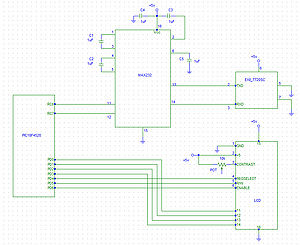
The image on the right is the circuit schematic showing the connections between all the components. An actual picture of the circuit is also shown.
The chips required for implementing this circuit are:
1) PIC 18F4520
2) MAX232N Dual EIA-232 Driver/Receiver
3) EXII 7720SC (touchscreen controller chip)
4) JHD 162A Parallel LCD
The PIC communicates with the touchscreen through the MAX232N chip. The MAX232N chip regulates the voltage of the input and output of the EXII 7720SC touchscreen chip(between -5V and +5V) to make it between 0 and +5V, since this is the signal range that is accepted by the PIC.
The PIC first transmits a "Format Tablet" command to the touchscreen chip, which tells the touchscreen what to transmit back to the PIC. When a finger makes contact with the touchscreen, the chip sends back a 10-byte string of hex values with the X and Y coordinates embedded in the first 5 bytes.