Difference between revisions of "IR communication between PICs"
(→Code) |
(→Code) |
||
| Line 68: | Line 68: | ||
== Code == |
== Code == |
||
Example code for a simple IR communication circuit w/o the use of a transceiver: |
|||
#include <18f4520.h> |
#include <18f4520.h> |
||
| Line 95: | Line 97: | ||
// Main program |
// Main program |
||
void main(void){ |
void main(void){ |
||
int i; |
int i; |
||
char rx; |
char rx; |
||
| Line 104: | Line 105: | ||
while(TRUE){ |
while(TRUE){ |
||
for(i=0;i<16;i++){ // Counts up from 0 to 15 and transmits to the first Encoder/Decoder. |
for(i=0;i<16;i++){ // Counts up from 0 to 15 and transmits to the first Encoder/Decoder. |
||
putc(i); // Listens to the second Encoder/Decoder, which is simply the original |
putc(i); // Listens to the second Encoder/Decoder, which is simply the original |
||
| Line 110: | Line 110: | ||
output_d((int8) rx); |
output_d((int8) rx); |
||
delay_ms(1000); |
delay_ms(1000); |
||
} |
} |
||
} |
} |
||
Revision as of 02:49, 6 February 2008
Original Assignment
Two PICs wired together can talk to each other using RS-232. Instead of wiring them together, we can use infrared transceivers so they communicate by IR. The goal of this project is to demonstrate bidirectional communication between two PICs using 38 kHz IR communication. Optional: show that these PICs can also receive data from a standard TV remote.
The Original Assignment indicates what you were assigned to do, and will eventually be erased from the final page.
Overview
The contents of this page explains how two PICs that are wired together can talk to each other using infrared transceivers, thus allowing them to communicate by IR. This projected demonstrates bidirectional communication between two PICs using 38 kHz IR communication. The UART within the PIC was used to send signals to the encoder/decoder, which communicated with the transceiver. This same technology can be used used to allow the PICs to receive data fro ma standard TV remote control.
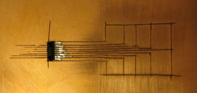
IR Chip The IR chip used for this project was a 0.95mm pitch surface mount chip, which was extremely difficult to work with. Both a copper-clad board an a SchmartBoard were used in attempts to mount this chip. A copper-clad board was etched by hand using an Exacto Knife as shown in the picture. This allowed for the IR chip to be soldered to the copper-clad board. There were leads coming from the IR chip to pins that were fanned out in such a way as to allow wires to easily be connected.
A SchmartBoard with part number 202-0004-01 was also obtained as a way of mounting the chip. The link to the website for SchmartBoards is provided in the External Links section.
- IR employed for short-range communication
- Beam is modulated to encode data
- Supports IrDA(?) speeds up to 115.2 kbits/s (SIR)
- Transceiver module consists of:
- PIN photodiode
- Infrared emitter (IRED)
- Low-power control IC
- IR EnDec uses PDIP, SOIC pacakge
Circuit
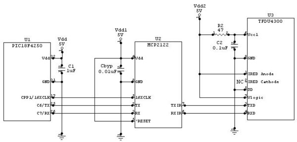
The Circuit Diagram shows the layout of the PIC, Encoder/Decoder, and IR Transceiver combination. Two of these set-ups are needed in order to have two independent circuits: one to transmit and one to receive data. The specifications of the circuit are as follows:
PIC
- VDD = 5.0V
- C1 = 1µF
- Pin 11 or 32 can be used for VDD
- Pin 12 or 31 can be used for GND
MCP2122: Encoder/Decoder
- VDD = 1.8V-5.5V
- CBYP = 0.01µF
IR Transceiver
- Vcc1 = 2.8V
- Vcc2 = 3.0V
- R2 = 47Ω
- C2 = 0.1µF
The links to the data sheets for the Encoder/Decoder and the IR Transceiver can be found in the External Links sections.
- PIC interfaces serially with EnDec
- EnDec connected to transceiver through a transmit pin, a receive pin, and a Vlogic pin?
- Transceiver manufactured by Vishay Semiconductors
- Part # TFDU4300
- EnDec manufactured by Microchip
- Part # MCP2122
Surface Mount Prototyping
- Transceiver lead pitch = 1.2mm/0.95mm/0.50mm/0.45mm?
- Multiple options for installation
- Schmart board
- Digikey board (need to find)
- Copper-clad board etching
- Funky pin adapter thing Prof. Peshkin gave us
- Funky adapter thing #2 Prof. Peshkin gave us
Limitations
- Transceiver cannot simultaneously transmit and receive
Code
Example code for a simple IR communication circuit w/o the use of a transceiver:
#include <18f4520.h>
#fuses HS,NOLVP,NOWDT,NOPROTECT
#use delay (clock=20000000)
#use rs232(baud=9600, xmit=PIN_C6, rcv=PIN_C7, stream=com_a) // Initializes the UART to 9600 bps
                                                            // (up to 115,200 bps)
// timed_getc() checks whether data is ready to be read.  If it's not the function returns a null
// character.  If you simply use getc(), the PIC might get slowed up if the data isn't ready right
// away.
char timed_getc(void){
   long timeout;

   int timeout_error = FALSE;
   timeout = 0;
   while(!kbhit() && (++timeout<50000))
      delay_us(10);
   if (kbhit())
      return(getc());
   else {
      timeout_error = TRUE;
      return(0);
   }
}
// Main program
void main(void){
   int i;
   char rx;
   setup_timer_2(T2_DIV_BY_1, 32, 16); // Provides a 151.3 kHz clock for the Encoder/Decoder, in
   setup_ccp1(CCP_PWM);                // order for it to know the baud rate of the UART. Should be
   set_pwm1_duty(16);                  // closer to 16 * 9600 = 153.6 kHz but the error is tolerable
   while(TRUE){
      for(i=0;i<16;i++){      // Counts up from 0 to 15 and transmits to the first Encoder/Decoder.
         putc(i);             // Listens to the second Encoder/Decoder, which is simply the original
         rx = timed_getc();   // message from the PIC, and displays the value on the LEDs/Port D.
         output_d((int8) rx);
         delay_ms(1000);
      }
   }
}
External Links and Further Reading

