Difference between revisions of "IR Tracker"
| Line 1: | Line 1: | ||
==Overview== |
|||
In Lab 5, you will create your own wiki page describing some useful PIC-related function. Good resources include this mechatronics wiki itself (some of these functions may be partially documented), the [http://www.ccsinfo.com PIC C compiler website] and sample code that comes with the compiler, the two manuals with the PIC C compiler, application notes at the [http://www.microchip.com Microchip website], and just general google searches on the topic. |
|||
The [http://info.hobbyengineering.com/specs/PX-GPSManualV1.1.pdf Parallax GPS (Global Positioning System) Receiver Module] is a fully integrated, low-cost unit with an on-board patch antenna. It provides standard, raw NMEA0183 (National Marine Electronics Association) strings or specific data from up to 12 satellites via its serial command interface. It can provide the current time, date, latitude, longitude, altitude, speed, travel direction, and other data. |
|||
Each page should have four headings: '''Original Assignment''', '''Overview''', '''Circuit''', and '''Code'''. See the [[Example Writeup: Analog Input]] for an example. The '''Original Assignment''' indicates what you were assigned to do, and will eventually be erased from the final page. The '''Overview''' is your rewritten version that clearly indicates what the page is about (to future students accessing the page) and should also include links to other good web sources of information on this topic, the '''Circuit''' shows a professional-looking circuit diagram including part numbers and where they can be obtained (and, where helpful, a photo of a neatly wired implementation of the circuit), and '''Code''' gives a listing of the liberally commented code, which should otherwise be as simple as possible (do not have extraneous lines of code that don't relate directly to the objective of the page). You may also wish to add a '''Further Reading''' section at the end of the page, with links to other useful sites on the topic. If not, you should make sure that your '''Overview''' has these links. |
|||
The Parallax GPS module was designed to be used with a Basic Stamp and to use two directional information transmission. In order to use this chip with a PIC, we will need to read in long serial strings containing all data and then parse the strings for important data to export. The PIC can use RS232 to read in the serial data and store a large array of all characters, which can then be parsed by searching for comma seperated values. |
|||
You are welcome to change the structure of your page to something other than these headings only if necessary to improve the clarity of the page. Don't erase the '''Original Assignment''' section. |
|||
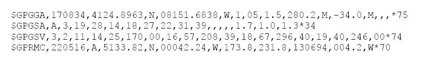
The NEMA strings this particular GPS outputs are GPGGA,GPGSA,GPGSV, and GPRMC in that order. For additional information about what data can be retrieved from these strings, go [http://home.mira.net/~gnb/gps/nmea.html here]. |
|||
Every topic that uses interrupts to implement a function should report how long it takes the interrupt to complete the service routine. One way to do this is to set a digital output pin "high" at the beginning of the interrupt service routine, then set it low at the end. Then look at this digital output on an oscilloscope. If the interrupt routine is occurring every 1 ms, then you should see a pulse every 1 ms, and the duration of the pulse tells you approximately how much time it takes your ISR to execute. If you don't clearly see a pulse of less than 1 ms every 1 ms, then your ISR may be taking more than its allotted time, and you need to either increase the time between ISR calls or decrease the complexity of your code in the ISR. '''Remember that bitwise operations such as &, |, !, >>, or << are fast, math operations on unsigned integers are slower, math operations on signed integers are slower still, math operations on floats are slower still, and trigonometric and other complex functions are very slow.''' If you have two different ISRs, say one at 1 ms intervals and another at 13 ms intervals (for example), use a different pin to time each and display the two channels simultaneously on your oscilloscope to understand the timing. |
|||
Here is an example string: |
|||
Your lab will be graded on functionality (how well you have completed the objective) and the usefulness of your wiki page (how clearly it is written and documented with images or other supporting material). If you use figures or information you found elsewhere on the web, give a citation (link) to the original source. '''Do not use copyrighted work!''' |
|||
[[image:GPS_Raw_Data_Stream|center]] |
|||
The goal of the project was to set up a one-way connection between the PIC and the GPS Receiver Module, in which the PIC interprets the raw data collected by the GPS Receiver Module and displays it in a user-friendly format on a parallel LCD (Liquid Crystal Display). Specifically for this project, there are three sets of information that can be displayed: Position (Latitude / Longitude); Time & Number of Satellites Detectable; Velocity / Direction of Movement. |
|||
=== Drawing Circuit Schematics === |
|||
We will first discuss the circuitry of PIC-GPS connection, followed by the method used to allow the PIC to gather data from the GPS Module, and finally how to display specific information on the parallel LCD. |
|||
There is no particular recommended software for drawing your circuit schematics. You can do it with almost any drawing program, with the pain of creating your own circuit elements. You can find a number of free schematic drawing programs, including Express PCB and PCB123, [http://www.freebyte.com/cad/cad.htm#electricalsystems here], including printed circuit board (PCB) layout. For this assignment, we just want '''schematics''', not PCB layouts, and they should be captured as images. Prof. Peshkin recommends trying [http://my.ece.ucsb.edu/bobsclass/2C/Simulation/circuit_maker.htm CircuitMaker], which is no longer supported but runs fine under Windows XP. [http://www.cadsoftusa.com/freeware.htm Eagle] runs under Windows, MacOS, and Linux. |
|||
==Circuit== |
|||
Other circuit drawing software: |
|||
*Microsoft Word (Draw symbols using the shapes and wires with the flowchart connectors. You can find an example [http://www.cs.cmu.edu/afs/cs.cmu.edu/academic/class/15251-s04/Site/Materials/Directions/circuits/ here].) |
|||
*[http://opencircuitdesign.com/xcircuit/ XCircuit]: Open source software that runs on Windows, Unix, and UNIX/X11 based Macs. |
|||
*Microsoft Visio: Not recommended, but it might do for simple circuits. |
|||
*[http://www.engr.uky.edu/~cathey/pspice061301.html PSpice Student]: Similar to Circuitmaker. |
|||
The four primary components used in this circuit are: |
|||
=== Lab 5 Assignments === |
|||
* Controller (PIC) |
|||
* [[Example Writeup: Analog Input]] |
|||
* Parallax GPS Receiver Module |
|||
* Liquid Crystal Display |
|||
* Three buttons |
|||
[[image:Parallax_GPS_Wiring_Digram.jpg|400px|center]] |
|||
Lab 5 assignments: |
|||
Image 1 shows the connection between the PIC and GPS Receiver Module. |
|||
* Team 22: [[IR communication between PICs]] |
|||
* Team 23: [[XBee radio communication between PICs]] |
|||
* Team 14: [[SPI communication between PICs]] |
|||
* Team 25: [[I2C communication between PICs]] |
|||
* Team 26: [[Serial communication with Matlab]] |
|||
* Team 15: [[Microphones]] |
|||
* Team 12: [[Ambient light color sensing]] |
|||
* Team 13: [[Controlling a seven segment display]] |
|||
* Team 21: [[Storing constant data in program memory]] |
|||
* Team 11: [[PIC computation time benchmarks]] |
|||
* Team 24: [[Stepper motor control with the PIC]] |
|||
* Team 25: [[Global Positioning System]] |
|||
<b>Note</b> that the pin labeled "Raw" needs to be grounded with a 1K resistor. The serial line also needs to be pulled high with a 1K resistor. |
|||
Future: |
|||
* [[Bootloader and wireless programming]] |
|||
[[image:Parallel_LCD_Wiring_Digram.jpg|400px|center]] |
|||
* [[RS-232 code]] (in Visual Basic, C, etc.) |
|||
Image 2 shows the connection between the PIC and LCD. |
|||
* [[Piezoactuators]] |
|||
* [[Ultrasonic ranging]] |
|||
[[image:GPS_Circuit.jpg|400px|center]] |
|||
* [[Speakers]] |
|||
Image 3 is an example of how to wire all these elements together on one breadboard |
|||
* [[Interfacing a PIC to a GPS module]] |
|||
* [[Wireless PIC bootloading]] |
|||
==Code== |
|||
* [[Reading RFID tags]] |
|||
* [[RF communication]] |
|||
[[media:ParallaxGPS.c|See full code here]] |
|||
* [[Barcode scanning]] |
|||
* [[Adding external RAM to your PIC]] |
|||
Include headers and set serial rate to 4800 baud |
|||
* Designing an 802.15.4 PCB for wireless communication between a PC and a PIC (this would consist of the PC's USB to RS232 (DB-9) adapter cable with a small PCB with a Maxstream xbee module and a MAX232N level-shifter chip, drawing power from the USB port). The PIC has another xbee module. |
|||
#include <18F4520.h> |
|||
#fuses HS,NOWDT,PUT,NOLVP |
|||
#use delay(clock=20000000) |
|||
#use rs232(baud=4800, rcv=PIN_C1) //can use any pin to read from GPS, but define it here |
|||
#include "flex_lcd.c" //included to allow easy writing to a parallel LCD display |
|||
Variable declarations and start of main loop |
|||
char letter[300]; |
|||
int go = 0,wait = 0,commacount = 0,dataoutput = 1,j = 0; |
|||
int16 i; |
|||
int16 comma[90]; |
|||
void main() |
|||
{ |
|||
lcd_init(); |
|||
while(TRUE) |
|||
{ |
|||
One of the most important aspects of this code is waiting for signal to return to high. Without this section, the rs232 command could end up in the middle of the output of the GPS and render all information unusable. This loop waits for the signal to remain high for over 2 bytes to ensure it is at the stop position before beginning to read. |
|||
for (wait=0;wait<20;) //for loop used to wait until signal has reset. 20*50us=1ms>two bytes of ones at 4800 baud |
|||
{ |
|||
if (input(PIN_C1)==1) |
|||
{ |
|||
wait++; |
|||
} |
|||
else if (input(pin_c1)==0) |
|||
{ |
|||
wait = 0; |
|||
} |
|||
delay_us(50); |
|||
} |
|||
After getting into the data loop, all data is recorded into a 300 character matrix letter |
|||
for(i=0;i<300;i++) //record 300 characters into letter matrix |
|||
{ |
|||
letter[i]= getc(); |
|||
} |
|||
The data is then parsed into sets of commas. |
|||
for(i=0;i<300;i++) //parse matrix for commas (ascii=44 for a comma) |
|||
{ |
|||
if (letter[i] == 44) |
|||
{ |
|||
comma[commacount] = i; |
|||
commacount++; |
|||
} |
|||
} |
|||
Counting variables are reset to zero at the end of the while loop |
|||
go = 0; //reset testing variables back to zero |
|||
commacount=0; |
|||
To finish the program, data must be converted into a usable format and output to the LCD screen. See full code above for an example of how to do this. |
|||
==References== |
|||
Parallax Info: http://info.hobbyengineering.com/specs/PX-GPSManualV1.1.pdf |
|||
Circuit Info: http://hades.mech.northwestern.edu/wiki/index.php/C_Example:_Parallel_Interfacing_with_LCDs |
|||
Revision as of 01:57, 8 March 2008
Overview
The Parallax GPS (Global Positioning System) Receiver Module is a fully integrated, low-cost unit with an on-board patch antenna. It provides standard, raw NMEA0183 (National Marine Electronics Association) strings or specific data from up to 12 satellites via its serial command interface. It can provide the current time, date, latitude, longitude, altitude, speed, travel direction, and other data.
The Parallax GPS module was designed to be used with a Basic Stamp and to use two directional information transmission. In order to use this chip with a PIC, we will need to read in long serial strings containing all data and then parse the strings for important data to export. The PIC can use RS232 to read in the serial data and store a large array of all characters, which can then be parsed by searching for comma seperated values.
The NEMA strings this particular GPS outputs are GPGGA,GPGSA,GPGSV, and GPRMC in that order. For additional information about what data can be retrieved from these strings, go here.
Here is an example string:
The goal of the project was to set up a one-way connection between the PIC and the GPS Receiver Module, in which the PIC interprets the raw data collected by the GPS Receiver Module and displays it in a user-friendly format on a parallel LCD (Liquid Crystal Display). Specifically for this project, there are three sets of information that can be displayed: Position (Latitude / Longitude); Time & Number of Satellites Detectable; Velocity / Direction of Movement.
We will first discuss the circuitry of PIC-GPS connection, followed by the method used to allow the PIC to gather data from the GPS Module, and finally how to display specific information on the parallel LCD.
Circuit
The four primary components used in this circuit are:
- Controller (PIC)
- Parallax GPS Receiver Module
- Liquid Crystal Display
- Three buttons

Image 1 shows the connection between the PIC and GPS Receiver Module.
Note that the pin labeled "Raw" needs to be grounded with a 1K resistor. The serial line also needs to be pulled high with a 1K resistor.

Image 2 shows the connection between the PIC and LCD.

Image 3 is an example of how to wire all these elements together on one breadboard
Code
Include headers and set serial rate to 4800 baud
  #include <18F4520.h>
  #fuses HS,NOWDT,PUT,NOLVP
  #use delay(clock=20000000)
  #use rs232(baud=4800, rcv=PIN_C1)        //can use any pin to read from GPS, but define it here
  #include "flex_lcd.c"                    //included to allow easy writing to a parallel LCD display
Variable declarations and start of main loop
  char letter[300];
  int go = 0,wait = 0,commacount = 0,dataoutput = 1,j = 0;
  int16 i;
  int16 comma[90];

  void main()
  {
     lcd_init();
     while(TRUE)
     {
One of the most important aspects of this code is waiting for signal to return to high. Without this section, the rs232 command could end up in the middle of the output of the GPS and render all information unusable. This loop waits for the signal to remain high for over 2 bytes to ensure it is at the stop position before beginning to read.
        for (wait=0;wait<20;)               //for loop used to wait until signal has reset.  20*50us=1ms>two bytes of ones at 4800 baud
        {
           if (input(PIN_C1)==1)
           {
              wait++;
           }
           else if (input(pin_c1)==0)
           {
              wait = 0;
           }
           delay_us(50);
        }
After getting into the data loop, all data is recorded into a 300 character matrix letter
        for(i=0;i<300;i++)                  //record 300 characters into letter matrix
        {
           letter[i]= getc();
        }
The data is then parsed into sets of commas.
        for(i=0;i<300;i++)                  //parse matrix for commas (ascii=44 for a comma)
        {
           if (letter[i] == 44)
           {
              comma[commacount] = i;
              commacount++;
           }
        }
Counting variables are reset to zero at the end of the while loop
        go = 0;                             //reset testing variables back to zero
        commacount=0;
To finish the program, data must be converted into a usable format and output to the LCD screen. See full code above for an example of how to do this.
References
Parallax Info: http://info.hobbyengineering.com/specs/PX-GPSManualV1.1.pdf
Circuit Info: http://hades.mech.northwestern.edu/wiki/index.php/C_Example:_Parallel_Interfacing_with_LCDs