Difference between revisions of "IR Tracker"
From Mech
Jump to navigationJump to search| Line 42: | Line 42: | ||
Structure: |
Structure: |
||
* Detecting Component: |
|||
* |
|||
** |
|||
[[image:Detecting_Component.jpg|600px|center]] |
|||
Plane: |
|||
Y-Axis Rotation: |
|||
X-Axis Rotation: |
|||
Base: |
|||
Actuators: |
|||
* Pitman Motors - constantly detect location of the emitter |
* Pitman Motors - constantly detect location of the emitter |
||
| ⚫ | |||
* Rotating Component: |
|||
The goals: |
|||
[[image:Rotating_Component.jpg|600px|center]] |
|||
| ⚫ | |||
==Electrical Design== |
==Electrical Design== |
||
Revision as of 14:39, 11 March 2008
Team Members
- Mark Straccia (Mechanical Engineering, Class of 2009)
- Matt Turpin (Mechanical Engineering, Class of 2009)
- Alice Zhao (Electrical Engineering, Class of 2008)
Overview
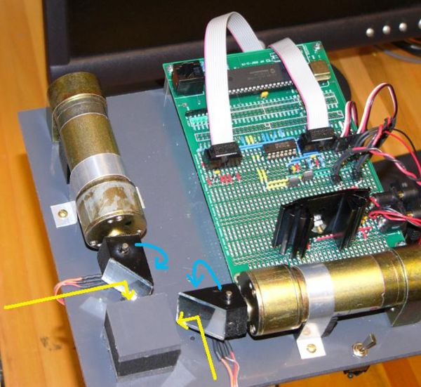
The goal of this project was to create a device that would follow a moving infrared light. The IR Tracker does this by continuously detecting the position of an infrared emitter in two axises, and then tracking the emitter with a laser.
The IR Tracker follows two major steps: (1) Identify the position of the IR emitter (2) Rotate the device to align itself with the IR emitter.
- (1) The IR Tracker finds the location of the maximum infrared intensity in both the x-axis and y-axis. Two encoders continuously record the position of the IR emitter based on intensity levels detected by two IT detectors.
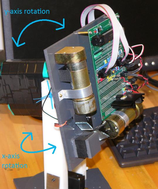
- (2) Given the information about the location of the IR emitter, the device rotates itself in two dimensions to adjusts its plane to be normal to the IR emitter. At this point, the laser should point to the IR emitter.
We will discuss the mechanical design, electrical design, PIC code, resulting project and our team reflections.
Mechanical Design
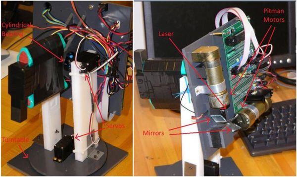
The primary components used in this circuit are:
- 2 Pitman Motors
- 2 RC Servos
- 1 Turntable (part number, vendor, cost, when available)
- 1 Cylindrical Bearing
- 1 Laser
- Mirror
- Plexiglas
Structure:
- Detecting Component:
- Pitman Motors - constantly detect location of the emitter
- Rotating Component:
- RC Servos - move the device to get align with emitter
Electrical Design
The primary components used in this circuit are:
- 1 PIC (18F4520)
- 1 H-Bridge (L298)
- 1 Inverting Schmidt Trigger (74HC14)
- 2 Hall Sensors
- 2 IR Detector / Emitter Pairs
Code
Results
Our resulting design:
Reflections
- More planning
- Simpler mechanical design
- More efficient code


