Difference between revisions of "I2C communication between PICs"
Matt Turpin (talk | contribs) (→Code) |
Matt Turpin (talk | contribs) (→Code) |
||
| Line 36: | Line 36: | ||
<b>Slave</b> |
<b>Slave</b> |
||
For the Slave PIC, we first need to define the output pins, define the name of the device and force hardware I2C communication. This device was randomly assigned name 0x14, but could have been just about any |
For the Slave PIC, we first need to define the output pins, define the name of the device and force hardware I2C communication. This device was randomly assigned name 0x14, but could have been just about any even hex number with a few exceptions noted below code. |
||
#use i2c(SLAVE, FAST, SCL=PIN_C3, SDA=PIN_C4, address=0x14, FORCE_HW) |
#use i2c(SLAVE, FAST, SCL=PIN_C3, SDA=PIN_C4, address=0x14, FORCE_HW) |
||
Revision as of 21:20, 2 February 2008
Original Assignment
Microcontrollers commonly talk to each other using protocols such as RS-232, SPI (for "serial peripheral interface"), I2C (or I^2C, "I squared C," for inter-integrated circuit), CAN bus, or other. This project is to demonstrate bidirectional I2C communication between two PICs. A demonstration might have the value of an analog input (potentiometer) at one PIC displayed as a "light bar" on the LEDs of the other PIC board, and simultaneously vice-versa.
Overview
Circuit
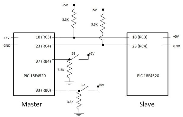
Below is a simple circuit diagram showing the master PIC with 2 close button switches. Note that pin 18 (RC3) is not brought out to the circuit board, but a wire can be soldered next to the PIC itself.
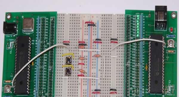
Here is an example of how to wire this.
Code
Full code with switch de-bouncing can be found here:
Master
For the Master PIC, we first need to define the output pins and force hardware I2C communication.
#use I2C(FAST, SCL=PIN_C3, SDA=PIN_C4, FORCE_HW) //using hardware I2C, built into the PIC, make sure to include this line in any master I2C program
To communicate with a device, we use the following lines of code where 0x14 is the device name.
  i2c_start();               //begin transmission
  i2c_write(0x14);           //select address of device to communicate with
  i2c_write(data);           //send actual data
  i2c_stop();                //terminate communication
Slave
For the Slave PIC, we first need to define the output pins, define the name of the device and force hardware I2C communication. This device was randomly assigned name 0x14, but could have been just about any even hex number with a few exceptions noted below code.
#use i2c(SLAVE, FAST, SCL=PIN_C3, SDA=PIN_C4, address=0x14, FORCE_HW)
The SSP interrupt is used for I2C communication. When the master begins to transmit data, the PIC goes into this interrupt.
  #INT_SSP                      //Interrupt for I2C activity
  void sspinterupt()
  {
     state = i2c_isr_state();   //Reading the type of transmission

     if(state < 0x80)           //Master is sending data
     {
        data = i2c_read();      //An array will be needed to store data if more than one byte is transferred
     }
     if(state == 0x80)          //Master is requesting data
     {
        i2c_write(data);
     }
     output_d(data);            //Output data to port D to visualize
  }
Somewhere in the main section of the program, probably right away, the SSP interrupt will need to be enabled.
  enable_interrupts(INT_SSP);
  enable_interrupts(GLOBAL);
Address exceptions:
  0000 000 1 START byte - for slow micros without I2C h/w
  0000 001 X CBUS address - a different bus protocol
  0000 010 X Reserved for different bus format
  0000 011 X Reserved for future purposes
  0000 1XX X Hs-mode master code
  1111 1XX X Reserved for future purposes
  1111 0XX X 10-bit slave addressing

