Difference between revisions of "I2C communication between PICs"
From Mech
Jump to navigationJump to searchMatt Turpin (talk | contribs) |
|||
| Line 6: | Line 6: | ||
== Circuit == |
== Circuit == |
||
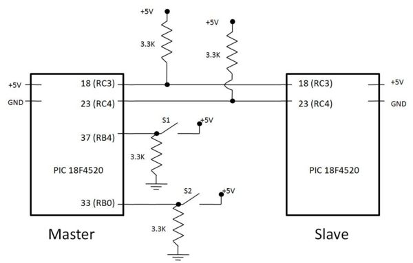
Below is a simple circuit diagram showing the master PIC with 2 close button switches. Note that pin 18 (RC3) is not brought out to the circuit board, but a wire can be soldered next to the PIC itself. |
|||
[[image:I2C Circuit Diagram.jpg|center|600px]] |
|||
== Code == |
== Code == |
||
Revision as of 19:34, 2 February 2008
Original Assignment
Microcontrollers commonly talk to each other using protocols such as RS-232, SPI (for "serial peripheral interface"), I2C (or I^2C, "I squared C," for inter-integrated circuit), CAN bus, or other. This project is to demonstrate bidirectional I2C communication between two PICs. A demonstration might have the value of an analog input (potentiometer) at one PIC displayed as a "light bar" on the LEDs of the other PIC board, and simultaneously vice-versa.
Overview
Circuit
Below is a simple circuit diagram showing the master PIC with 2 close button switches. Note that pin 18 (RC3) is not brought out to the circuit board, but a wire can be soldered next to the PIC itself.
