Filtering with the LMF100
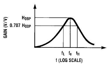
The LMF100 is a chip that contains two independent switched capacitor filters. With just a few added external resistors, it can be used to create 1st-4th order lowpass, highpass, notch, and bandpass filters. Independently each filter is either first or second order (depending on the external resistor configuration), but they can be cascaded to create up to a fourth order filter. This page will focus primarily on what the device's datasheet calls "Mode 1" (a bandpass filter), although the other modes described in the datasheet are quite similar. The bandpass gain plot is shown to the right.
In general, the second order bandpass response is given by:
where is the gain of the filter at the center frequency , is the quality factor of the complex pole pair, and is the center frequency in rad/sec.
For each mode described in the datasheet this simplifies down to a couple of governing equations relating external resistances to the properties of the bandpass filter. If the chip is wired for Mode 1 operation, then the important equations are:
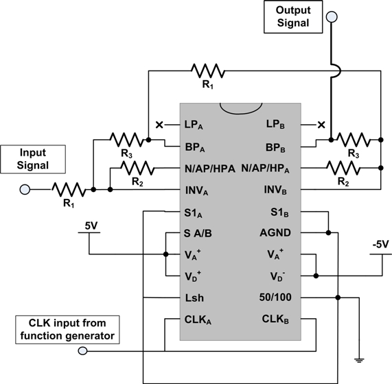
From these equations you can determine the frequency of the incoming clock signal needed for a desired center frequency, and the values of resistors needed to set a desired center freqency gain and bandwidth (or alternately, Q). If the chip is wired as two cascaded, Mode 1, second order, bandpass filters, as shown in below, and each filter is constructed with the same external resistors, the fourth order filter response is:
The primary advantage to using the LMF100 with the PIC or a waveform generator like the AD9833 is that it allows the filter to be tuned directly by the PIC, by varying the input clock frequency. Beware when doing this, however, because by changing the center frequency of the filter you will also change your bandwidth in order to keep the constant Q value that is set by the external resistors.


![{\displaystyle H_{BP}(s)=\left[{\frac {H_{OBP}\cdot {\frac {\omega _{0}}{Q}}\cdot s}{s^{2}+{\frac {s\omega _{0}}{Q}}+\omega _{0}^{2}}}\right]^{2}}](https://wikimedia.org/api/rest_v1/media/math/render/svg/d1b7ca48bdb2ebb3258bb7289d7c35f61182371e)
