Ferrofluid Art Display
Overview
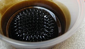
The goal of this project was to create a visually appealing and mathematically interesting art installation using a special kind of magnetically sensitive fluid called a ferrofluid. The project was inspired by the work of two Japanese researchers-turned-artists, Sachiko Kodama and Yasushi Miyajima, whose most recent creation, Morpho Towers, uses the magnetic properties of ferrofluids to visualize complex waveforms in three dimensions.
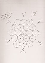
Wanting to replicate the same effect, but include an additional level of control, we designed a housing that contained 19 individually addressable solenoids arranged in a symmetrical heaxgonal array, and mounted small neodymium-iron-boride magnets to the shafts of each electromechanical element. Then, with the help of a few specialized circuits and some custom-written software running on the NU32 PIC, it was our hope to bring all 19 elements under computerized control via a graphical user interface running on a laboratory PC. Through this interface, a user or another piece of software could actuate the solenoids up and down, changing the strength of the magnetic field penetrating the ferrofluid, thus altering the shape of the fluid's surface.
Team Members
- Todd H. Poole (Mechanical Engineering & Electrical Engineering, Class of 2010)
- Katy Powers (Mechanical Engineering, Class of 2010)
- Max Willer (Mechanical Engineering, Class of 2011)
Physical & Mechanical Design
Like all large projects, our art display underwent several stages of design evolution before settling into its final form. Each stage was marked by a specific physical design, with each design possessing its own advantages and disadvantages. As time went on, the designs changed to accommodate an update in our direction, to take advantage of newly acquired supplies or materials, or to overcome unanticipated difficulties or errors.
We knew from the beginning that we wanted to incorporate the concept of symmetry into our final display piece. We were eager to avoid asymmetrical magnetic fields because we knew that, theoretically, they would be difficult to construct without increasing the cost and complexity of our proposal, and that they would be less aesthetically pleasing (by our own subjective judgment) than symmetrical ones.
Accordingly, all of our early sketches included some form of fundamental symmetry in their physical design.
Physical Design
Initial Ideas
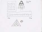
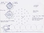
In our first brainstorming session, we explored the possibility of using one very large electromagnet (a la Morpho Towers) and an equally large geometrically complex cone of iron to house the magnet in as well as a series of several basic geometric shapes for an array of magnets.
For the single electromagnet concept, we hypothesized:
- Pros
- Simple (there would be only one element to focus on)
- Electrically controllable (by varying the voltage across the electromagnet, we could increase or decrease the strength of the magnetic field)
- Inherently symmetrical (rotational symmetry about the conical axis)
- Cons
- Expensive (some large electromagnets we were interested in purchasing easily cost anywhere between $200.00 to $1000.00, well above our budget of $100.00)
- Very specific material requirements (would require a large conic chunk of iron (heavy) with multiple points possessing high degrees of curvature (difficult to lathe, rare to find) in order to create anything more visually interesting than a simple blob)
For the simple geometric array of magnets, we hypothesized:
- Pros
- Less expensive (for the price of one large electromagnet, we could buy 25 solenoids or 25 hobby servos)
- More elements yields more control (individually actuating each element would give us a greater degree of control over the magnetic field normal to the fluid surface thus possibly resulting in more interesting fluid shapes)
- Still relatively simple to construct (build one element, then replicate it the necessary number of times)
- Cons
- High current draw (the first solenoids we found in the supply closet required 6 amps)
- Prohibitively large in size (the solenoids we found were 5 inches tall)
Mature Concepts
After spending some time weighing the pro's and con's of each idea listed above, we ultimately decided to pursue our array of magnets concept. We decided that a circular array would yield the most aesthetically pleasing forms of symmetry, and would afford us the opportunity to simplify some of our display behavior ideas by incorporating polar coordinates.
For the circular array concept, we hypothesized:
- Pros
- Simple and easy to understand
- Symmetrical (although not a perfect circle in practice, in theory there would be many lines of symmetry)
- Pattern display flexibility (we could display patterns radially, rotate them about a central axis, or display them in standard (x,y) coordinates with great ease)
- Cons
- Time consuming to construct (29 elements to CNC, mill, sand, drill, and fit)
- Time consuming to create control circuitry for (29 PIC outputs, 29 NAND gates, 29 H-Bridges)
- Time consuming to program (29 methods for 29 solenoids, plus FFT)
- Moderately high current draw (at .3 amps per solenoid, the entire display would require 8.7 amps)
Final Design
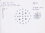
Once our milestone had passed, we decided to slightly alter our array's design, changing its shape from a circle to a hexagon. We reasoned that this would allow us to not only save time by reducing the number of components necessary to maintain a reasonable degree of symmetry, but also reduce the amount of current required to power our display (drawing close to 9 amps became a real concern after we drew just less than a third of that with a trial run of 6 elements.)
Modifying our design, we reasoned that a hexagonal shape would best serve our project
Modifying our design For the hexagonal array concept, we hypothesized:
- Pros
- Fewer components (less time spent on construction, less time spent on circuitry, less time spent programming)
- Smaller material costs (many of the materials we needed for construction would be easily obtainable through the parts bins in the laboratory, and the scrap heap in the shop)
- Still relatively symmetrical
- Still posses pattern display flexibility
- Cons
- Difficult to create true standing waves (minor)
Ultimately, we felt like this was a great adjustment. Reducing the number of elements from 29 to 19 and changing our array's shape from a circle to a hexagon not only helped us stay on track in terms of time, but measurably simplified many of our individual tasks.
Mechanical Design
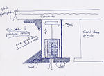
The mechanical design of our project relied on the behavior of 19 common electromechanical solenoids.
Each solenoid consisted of an electromagnetically inductive coil wound around a hollow cylinder into which a movable iron rod could be inserted. The coil was shaped such that the rod can be moved in and out of the center, altering the coil's inductance and thereby becoming an electromagnet.
The magnetic field induced by the current carrying coil inside the solenoid resulted a mechanical force acting on the rod, and was enough to push our magnets up out of their housing and close to the surface of the fluid. Reversing the current reversed the magnetic field and was enough to pull our rod-magnet combination back down into the housing of our display, and away from the fluid.
Although somewhat difficult to envision in one's mind, imagine a rudimentary form of electromechanical Whack-A-Mole. See this video for a demonstration of one of these solenoids in action with its associated control and power circuitry.
The following materials were used in the physical and mechanical construction of our display:
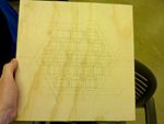
- 2x 1.5" thick, 12" x 12" sheets plywood, obtained in the NU Shop, free of charge.
- 1x 1/8" thick, 12" x 12" sheets polycarbonate (Part No. 8574K25), obtained through McMaster-Carr, for $6.66 a sheet.
- 19x Jameco Push Solenoid (SOLENOID,OPEN FRAME-PULL,12V4W,2/8MM SHFT DIA,6MM STRK - Part No. 262271), obtained through Jameco, for $8.75 a solenoid.
- 19x 3/4" diameter x 1/8" thick neodymium iron boron disc magnets (Part No. ND045), obtained through Magnet4Less, for $0.68 per magnet.
Electrical Design
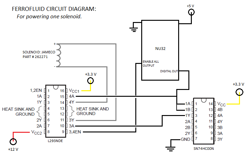
Our electronics system consisted of:
- One NU32 board: Introduction to the PIC32
- 19 solenoids: Jameco Part #262271
- 10 L293NDE Quad-half-bridges: Datasheet
- 5 SN74HC00N NAND Integrated Circuits: Datasheet
- Inputs came from twenty of the PIC's digital output pins. 19 of those went to the NAND logic chips while the last one went to a hub controlling the enable pins of the H-Bridges.
- The NAND's were set up so that the input from the PIC went to both pins of the input so that the opposite signal would come out of the output. Both the input and the output of the NAND chip would then go to 2 inputs of the quad-half-bridge.
- The H-bridge would then output either a +12V or a -12V (forward or reverse) across the solenoid dependent on a high or low output from the PIC.
- The H-bridge is also connected to the enable voltage. Controlled by the PIC, the enable voltage, when high, would allow current to flow through the half-bridges. When low, no current would flow. This made it so that current would not flow at all times, just when the solenoids were switching position.
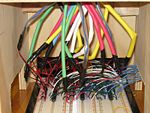
Picture of circuit for 4 solenoids goes.
Code
The code for the display setup consists of a GUI on the PC allowing the user to select which solenoids to turn on and off and code on the PIC to control the solenoids.
Processing
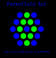
The PC side of the user interface was created with Processing, an open source programming environment with many options for interesting visual display. This code creates a display of circles arranged in the same way as the solenoids in our hardware, which will change from blue to green when clicked and output a character via RS232 to the PIC.
//Katy Powers
//3/11/2010
//ME 333 Ferrofluid Art GUI
//Lots of code taken from processing website and previous ME 333 labs..thanks!

// add the serial library
import processing.serial.*;
Serial[] myPorts = new Serial[1];

//setup parameters for hexagonal array
//cx,cy define center position, rc is circle radius, sp is how far apart they are
int cx = 250;
int cy = 250;
int rc = 50;
int sp = 10;


//circleX and circleY store center locations of every circle in array
//solenoidON stores state of solenoid
//chararr stores characters corresponding to each solenoid
int[] circleX = {cx, cx + rc + sp,cx + 2*(rc + sp),cx - (rc + sp),cx - 2*(rc + sp),cx + rc/2 + sp/2,
cx + 3*rc/2 + 3*sp/2,cx - (rc/2 + sp/2),cx - (3*rc/2 + 3*sp/2),cx,cx+rc+sp, cx - (rc+sp),
cx + rc/2 + sp/2, cx + 3*rc/2 + 3*sp/2,cx - (rc/2 + sp/2),cx - (3*rc/2 + 3*sp/2),cx,
cx + rc + sp,cx-(rc + sp)};

int[] circleY = {cy,cy,cy,cy,cy,cy + rc +sp,cy + rc +sp,cy + rc +sp,cy + rc +sp,cy + 2*(rc+sp),
cy + 2*(rc+sp), cy + 2*(rc+sp),cy - (rc +sp),cy - (rc +sp),cy - (rc +sp),cy - (rc +sp),
cy - 2*(rc+sp),cy - 2*(rc+sp),cy - 2*(rc+sp)};

int[] solenoidON = new int[19];
char[] chararr = {'a','b','c','d','e','f','g','h','i','j','k','l','m','n','o','p','q','r','s'};
PFont font;
PFont smallfont;


void setup()
{
InitSerial();
background(0);
font = loadFont("FangSong-48.vlw");
smallfont = loadFont("FangSong-16.vlw");
size(500,500);
textAlign(CENTER);
for (int i = 0; i < 19; i = i+1){ //zero array of solenoid values, mouse state data
  solenoidON[i] = 0;
}
rectMode(CENTER);
}

void draw()
{
  fill(0,0,255);
  textFont(font, 48);
  text("Ferrofluid Art", cx, cy-200);
  textFont(smallfont, 16);
  text("Click a circle to make patterns in the Ferrofluid", cx, cy + 200);
  hexagon(cx,cy,rc,sp, solenoidON);

}

void hexagon(int cx, int cy, int rc, int sp, int[] sols) //draws hexagon of cirlces
{
for (int i = 0; i < 19; i = i+1){
  if(sols[i] == 0) {fill(0,0,255);}
  else {fill(0,255,0);}
  ellipse(circleX[i], circleY[i], rc, rc);
}

}

void mousePressed() //executes when mouse is pressed, much like an interrupt routine
{
  float disX, disY;
  for (int i = 0; i < 19; i = i+1){ //see where mouse is
    disX = circleX[i] - mouseX;
    disY = circleY[i] - mouseY;
    if(sqrt(sq(disX) + sq(disY)) < rc/2 ) { //if mouse is in circle, toggle state and send character
      solenoidON[i] = 1 - solenoidON[i];
      myPorts[0].write(chararr[i]);
      println(chararr[i]); //to debug
       }
    }
}
PIC
The PIC side of the code runs an infinite while loop, executing an interrupt routine every time a character is received from the RS232. The PIC then updates the state of all the solenoids, sets the enable pins in the electrical circuit high for a short period of time in order to allow the solenoids to receive power, and then sets the enable pins low to prevent overheating.
/**Ferrofluid Art Project Code**********************************/
/* Katy Powers Winter 2010 */

/** INCLUDES ***************************************************/
#include "HardwareProfile.h"
#include "LCD.h" //needed for Delayms

/** Constants **************************************************/

#define TRUE 		1
#define FALSE		0

#define ENABLE1 LATDbits.LATD1 //Enable pins for H bridge circuit
#define ENABLE2 LATDbits.LATD2
#define OUT1   LATBbits.LATB11 //Output pins for solenoid control
#define OUT2   LATBbits.LATB10
#define OUT3   LATBbits.LATB9
#define OUT4   LATBbits.LATB8
#define OUT5   LATAbits.LATA10
#define OUT6   LATAbits.LATA9
#define OUT7   LATBbits.LATB7
#define OUT8   LATBbits.LATB6
#define OUT9   LATBbits.LATB0
#define OUT10  LATBbits.LATB1
#define OUT11  LATBbits.LATB2
#define OUT12  LATBbits.LATB3
#define OUT13  LATBbits.LATB5
#define OUT14  LATEbits.LATE9
#define OUT15  LATEbits.LATE8
#define OUT16  LATGbits.LATG9
#define OUT17  LATGbits.LATG8
#define OUT18  LATGbits.LATG7
#define OUT19  LATGbits.LATG6

#define DESIRED_BAUDRATE    	(19200)      // The desired BaudRate


/** Function Declarations **************************************/
void initInterruptController();

void initUART2(int pbClk);

void sendDataRS232(void);

void setSols(void); //sets solenoids on and off depending on global variable sols

/** Global Variables *******************************************/

int sols[19]; //vector to store if solenoids are on or off

/** Main Function **********************************************/

int main(void)
{
	int	pbClk;
	int i;
	// Configure the proper PB frequency and the number of wait states
	pbClk = SYSTEMConfigPerformance(SYS_FREQ);
	AD1PCFG = 0xFFFF; //this line sets up the B bits as digital outputs

	TRISAbits.TRISA10 = 0; //set all solenoid and enable output pins to output
	TRISAbits.TRISA9 = 0;
	TRISBbits.TRISB11 = 0;
	TRISBbits.TRISB10 = 0;
	TRISBbits.TRISB9 = 0;
	TRISBbits.TRISB8 = 0;
	TRISBbits.TRISB7 = 0;
	TRISBbits.TRISB6 = 0;
	TRISBbits.TRISB5 = 0;
	TRISBbits.TRISB3 = 0;
	TRISBbits.TRISB2 = 0;
	TRISBbits.TRISB1 = 0;
	TRISEbits.TRISE9 = 0;
	TRISEbits.TRISE8 = 0;
	TRISGbits.TRISG8 = 0;
	TRISGbits.TRISG7 = 0;
	TRISGbits.TRISG6 = 0;
	TRISBbits.TRISB0 = 0;
	TRISGbits.TRISG9 = 0;
	TRISDbits.TRISD1 = 0;
	TRISDbits.TRISD2 = 0;

	OUT1 = 0; //initialize outputs to low
	OUT2 = 0;
    	OUT3 = 0;
	OUT4 = 0;
        OUT5 = 0;
	OUT6 = 0;
        OUT7 = 0;
	OUT8 = 0;
	OUT9 = 0;
	OUT10 = 0;
	OUT11 = 0;
	OUT12 = 0;
    	OUT13 = 0;
	OUT14 = 0;
	OUT15 = 0;
	OUT16 = 0;
        OUT17 = 0;
	OUT18 = 0;
	OUT19 = 0;

	//also initialize sols array to 0
	for(i = 0; i < 19; i++){
	sols[i] = 0;
	}
	setSols(); //this is probably redundant

	mInitAllLEDs();


	initUART2(pbClk);
	INTEnableSystemMultiVectoredInt();

	while(1)
	{
	  1;//just keep going and wait for interrupts from RS232
	} //end main

}
/** Interrupt Handlers *****************************************/

void __ISR(_UART2_VECTOR, ipl2) IntUart2Handler(void)
{
	int i;
       unsigned char data2; //store character received from PC
	char chararr[19] =  {'a','b','c','d','e','f','g','h','i','j','k','l','m','n','o','p','q','r','s'};
 //array of characters for comparison
	// Is this an RX interrupt?
	if(mU2RXGetIntFlag())
	{
		// Clear the RX interrupt Flag
	    mU2RXClearIntFlag();

		data2 = ReadUART2(); //get character

		// Toggle LED to indicate UART activity
		mLED_1_Toggle();

		for(i = 0; i<19; i++){
		if (data2 ==(int) chararr[i]){ sols[i] = 1 - sols[i];} //toggle solenoid
                                                      //corresponding to character received
		}
		setSols(); //update all solenoids

	}

	// We don't care about TX interrupt
	if ( mU2TXGetIntFlag() )
	{
		mU2TXClearIntFlag();
	}
}


/** Other Functions ********************************************/

void initUART2(int pbClk)
{
	 // define setup Configuration 1 for OpenUARTx
		// Module Enable
		// Work in IDLE mode
		// Communication through usual pins
		// Disable wake-up
		// Loop back disabled
		// Input to Capture module from ICx pin
		// no parity 8 bit
		// 1 stop bit
		// IRDA encoder and decoder disabled
		// CTS and RTS pins are disabled
		// UxRX idle state is '1'
		// 16x baud clock - normal speed
	#define config1 	UART_EN | UART_IDLE_CON | UART_RX_TX | UART_DIS_WAKE |
UART_DIS_LOOPBACK | UART_DIS_ABAUD | UART_NO_PAR_8BIT | UART_1STOPBIT | UART_IRDA_DIS |
UART_DIS_BCLK_CTS_RTS| UART_NORMAL_RX | UART_BRGH_SIXTEEN

 	 // define setup Configuration 2 for OpenUARTx
		// IrDA encoded UxTX idle state is '0'
		// Enable UxRX pin
		// Enable UxTX pin
		// Interrupt on transfer of every character to TSR
		// Interrupt on every char received
		// Disable 9-bit address detect
		// Rx Buffer Over run status bit clear
	 #define config2		UART_TX_PIN_LOW | UART_RX_ENABLE | UART_TX_ENABLE |
UART_INT_TX | UART_INT_RX_CHAR | UART_ADR_DETECT_DIS | UART_RX_OVERRUN_CLEAR

	// Open UART2 with config1 and config2
	OpenUART2( config1, config2, pbClk/16/DESIRED_BAUDRATE-1);	// calculate actual BAUD
generate value.

	// Configure UART2 RX Interrupt with priority 2
	ConfigIntUART2(UART_INT_PR2 | UART_RX_INT_EN);
}

void setSols(){
	OUT1 = sols[0]; //set all outputs to correct value
	OUT2 = sols[1];
	OUT3 = sols[2];
	OUT4 = sols[3];
	OUT5 = sols[4];
	OUT6 = sols[5];
	OUT7 = sols[6];
	OUT8 = sols[7];
	OUT9 = sols[8];
	OUT10 = sols[9];
	OUT11 = sols[10];
	OUT12 = sols[11];
	OUT13 = sols[12];
	OUT14 = sols[13];
	OUT15 = sols[14];
	OUT16 = sols[15];
	OUT17 = sols[16];
	OUT18 = sols[17];
	OUT19 = sols[18];
	ENABLE1 = 1; //turn on enable pins
	ENABLE2 = 1;
	Delayms(500); //wait for half a second for solenoids to change position
	ENABLE1 = 0; //turn off enable pins
	ENABLE2 = 0;
}
Results
Summary of Parts
- Electrical
The electric circuit was fully functional at the end of construction, with each solenoid responding to a high or low signal coming from where the PIC output would enter the NAND chip. If a 3.3 V signal came from the PIC output, 12 V would go across the solenoid. If a 0 V signal came from the PIC, a -12 V signal would go across the solenoid.
- Mechanical
The mechanical setup was also fully functional at the end of construction. Each solenoid fit snugly into their insert with the leads coming out in a shrink-wrapped conduit. The polycarbonate container was bent and sealed with epoxy and there was a wooden base so that the electronics would be housed conveniently under everything.
- Coding
The attempted Fast Fourier Transform coding was working by the end of construction, lighting up LED lights when certain frequencies were active. Our idea for the music response mode was to have the FFT recognize the melody and output the musical note to the corresponding solenoid on the outside diameter of the hexagon. The middle solenoids would be activating at random.
The user interface was also working. The Processing application's solenoid control buttons were functional and sent data over the RS232 cable to the PIC. The final idea was to have it as a user option whether to go into music response mode or manually control the solenoids.
Combining the Parts
- Combining Electrical with Mechanical
While all of the solenoids fit snugly into their inserts, we found that the magnets were interfering with each other from their positions. We had all of the cylindrical magnets facing the same polarity (all of the north ends of the magnets faced up). Because of this arrangement, the magnets felt a repulsive force from the other magnets. We found we were able to push the solenoids up (boosted by the magnetic force from the other magnets) but we were unable to bring them down due to the extra force overcoming the force from the solenoid's pull. Since we had tested the forces on the solenoids separately, we did not think to check the forces on them when in the arrangement, but it made for a project that was only half functional.
In addition, we attempted to help overcome the extra force in two ways. First, by increasing the padding space between the bottom of the ferrofluid container and the magnets. This way the solenoid would be more in its most efficient spot, and the magnetic force from the ferrofluid would be less. Second, we removed one of the magnets from each solenoid arrangement (only one magnet instead of two) to try and lessen the magnetic forces between the magnets. Not only did this not work, but it made it so that the magnets then had little effect on the ferrofluid (slight bumps instead of spiky designs).
- Combining Electrical with Coding
Had we been able to take more time with this interface, the problems would have been easy fixes. As it was though, the wires of the solenoids coming down from the hardware enclosure got mixed up when getting connected to the H-bridge outputs. This made it so the NAND inputs did not match up with the PIC outputs they should have.
Another small problem we had was that the solenoids enabled time was too low. Since each solenoid takes around .2 A at 12 V, it would take a lot of power to power all 19 solenoids at once. So we used an enable pin to enable and disable all the H-Bridges at once. This way, we could use only one pin for each solenoid, and the power wouldn't be on at all times, only when solenoids needed to change positions. Since the time we had the enable pin set to high was too short, the solenoids didn't have enough time to push up the magnets. This was a programmed constant and could have been optimized with more testing.
- Combining the Coding with the User Interface
While the FFT code worked in concept, in reality it took too long to compute the main frequencies of a song that was playing. Without some sort of buffer or faster code, the melody might be recognized, just too late.
The User Interface worked on the PC through a Processing program and indicated what mode the user was in as well as which solenoids were up or down.
Reflections
Todd
