Difference between revisions of "E-Puck Color Sensing Project"
JamesYeung (talk | contribs) |
|||
| (21 intermediate revisions by one other user not shown) | |||
| Line 1: | Line 1: | ||
[[Image: |
[[Image:e-puck_color_sensing_project.jpg|right|e-Puck with the Zigbee module add-on board and red color sensor.|thumb|400px]] |
||
==Overview== |
==Overview== |
||
Project by: James Yeung, Electrical Engineering, Class of 2009.<br> |
|||
Last updated: June 16, 2008 |
|||
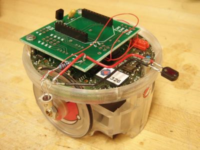
The goal of this project was to have the e-Puck roll around on the floor under a projected image, take sensor readings with one of the R G or B sensors, send back the position and color data to a listening PC by RS232 protocol via bluetooth, and occasionally receive from the PC new (x,y,theta) data on the actual position of the e-Puck (between receiving this data, the robot keeps track of its position by dead reckoning; upon receiving the data, the robot resets its estimated position to the new data). The robot had to roll around to cover the whole projected image (which is unchanging), and at the end of the run, the host PC had to display the reconstructed image and plot the error from the actual image. On the host PC side, MATLAB was used as an interface to talk to the e-Puck and generate the appropriate graphs. |
The goal of this project was to have the e-Puck roll around on the floor under a projected image, take sensor readings with one of the R G or B sensors, send back the position and color data to a listening PC by RS232 protocol via bluetooth, and occasionally receive from the PC new (x,y,theta) data on the actual position of the e-Puck (between receiving this data, the robot keeps track of its position by dead reckoning; upon receiving the data, the robot resets its estimated position to the new data). The robot had to roll around to cover the whole projected image (which is unchanging), and at the end of the run, the host PC had to display the reconstructed image and plot the error from the actual image. On the host PC side, MATLAB was used as an interface to talk to the e-Puck and generate the appropriate graphs. |
||
| Line 24: | Line 27: | ||
===Attempt 3=== |
===Attempt 3=== |
||
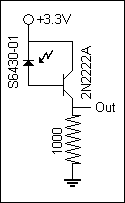
This was the third and final attempted circuitry. I used a simple transistor to give the output roughly a 200x current gain, which allowed me to use a much smaller resistor to lower the output impedance. Although I did not look into this in great detail, it seems like there was a huge variance in the amount of current gain between individual transistors. Furthermore, different resistor values work better under different light conditions. So a trim |
This was the third and final attempted circuitry. I used a simple transistor to give the output roughly a 200x current gain, which allowed me to use a much smaller resistor to lower the output impedance. Although I did not look into this in great detail, it seems like there was a huge variance in the amount of current gain between individual transistors. Furthermore, different resistor values work better under different light conditions. So a trim-pot might be a better design if you plan on reproducing this circuit.<br><br> |
||
==Code== |
==Code== |
||
[http://hades.mech.northwestern.edu/wiki/images/0/0e/E-puck_color_sensing_project_source.rar Full source code] |
|||
===Overview=== |
===Overview=== |
||
| Line 32: | Line 36: | ||
===Code for e-Puck=== |
===Code for e-Puck=== |
||
This code borrows many functions from the standard e-Puck library and other added functions by Prof. Lynch in the NUtest.c version of the e-Puck code. |
|||
<pre> |
|||
===Code for MATLAB=== |
|||
// main.c for RedScan project |
|||
// James Yeung |
|||
// 6/1/2008 |
|||
// |
|||
// This code is for the e-puck to be used in conjunction with RedScan.m in MATLAB. It will control the e-Puck to set up the bluetooth |
|||
// connection with PC, calibrate the sensor, perform the lawn mowing pattern, send sensor readings to PC, and allow user update of |
|||
// position/heading coordinates. |
|||
#include <p30f6014A.h> // contains register definitions, etc., for the dsPIC |
|||
==Results== |
|||
#include <string.h> // string manipulation |
|||
#include <ctype.h> // contains the "toupper" command to convert lower to uppercase |
|||
#include <stdio.h> // standard I/O routines |
|||
#include <math.h> // math functions like sqrt, cos, etc. |
|||
#include <a_d/advance_ad_scan/e_ad_conv.h> // reads the A/D channelsp |
|||
#include <a_d/advance_ad_scan/e_acc.h> // reads the 3 accelerometer channels (using e_ad_conv) |
|||
#include <motor_led/e_epuck_ports.h> // gives mnemonic names to pins, defines simple asm functions |
|||
#include <motor_led/e_init_port.h> // initializes the port values and whether input or output |
|||
#include <motor_led/advance_one_timer/e_led.h> // uses the LED's with interrupts, to allow blinking, etc. |
|||
#include <motor_led/advance_one_timer/e_motors_NU.h> // interrupt-driven motor routines (step every x millisecs, e.g.) |
|||
#include <motor_led/advance_one_timer/e_agenda_NU.h> // manages "agenda" (the interrupt routines) |
|||
#include <uart/e_uart_char.h> // uses the uarts for comm (in this case, bluetooth with PC) |
|||
#define uart_send_static_text(msg) do { e_send_uart1_char(msg,sizeof(msg)-1); while(e_uart1_sending()); } while(0) |
|||
#define uart_send_text(msg) do { e_send_uart1_char(msg,strlen(msg)); while(e_uart1_sending()); } while(0) |
|||
#define SENSOR_OFFSET 4.5 |
|||
static char buffer[52*39*2+3+80]; |
|||
==Code== |
|||
int i; |
|||
[http://hades.mech.northwestern.edu/wiki/images/6/6e/SteelToeCode.c Full source code] |
|||
char c='z'; |
|||
float x,y,theta,dist,heading,diff,x_target,y_target,theta_target,speed,j; |
|||
// return the angle limited to [-PI, PI]; PI defined in e_motors_NU.h |
|||
===Overview Comments=== |
|||
float anglelimit(float ang) { |
|||
<pre> |
|||
while (ang<-PI) ang += 2.0*PI; |
|||
/*//////////////////////////////////////////////////////////////////////////////////////////////////////////// |
|||
while (ang>PI) ang -= 2.0*PI; |
|||
stiffness_control.c, j.yeung, a.care, e.nickel 2008-01-31 |
|||
return ang; |
|||
} |
|||
void go_to(float x_target, float y_target, float theta_target){ |
|||
This code is to be used with the programmable stiffness joint. |
|||
theta_target = anglelimit(theta_target*DEG2RAD); |
|||
e_get_configuration(&x,&y,&theta); |
|||
dist = sqrt((x-x_target)*(x-x_target)+(y-y_target)*(y-y_target)); |
|||
if (dist>0.1) { // don't do the first rotate and translate if goal is too close |
|||
heading = atan2(y_target-y,x_target-x); |
|||
diff = anglelimit(heading-theta); |
|||
if (diff<(-0.5*PI)) { |
|||
dist = -dist; |
|||
diff = diff+PI; |
|||
} |
|||
else if (diff>(0.5*PI)) { |
|||
dist = -dist; |
|||
diff = diff-PI; |
|||
} |
|||
speed = e_rotate(diff,2.0); // rotate at 2 radians/sec |
|||
while((e_get_goal_active_left()!=0) || (e_get_goal_active_right()!=0)); |
|||
theta = theta + diff; |
|||
speed = e_translate(dist,4.0); // translate at 4 cm/sec (max around 12.9 cm/sec) |
|||
while((e_get_goal_active_left()!=0) || (e_get_goal_active_right()!=0)); |
|||
} |
|||
diff = anglelimit(theta_target - theta); |
|||
if (abs(diff)>0.02) { // don't do final rotate if already close to desired angle |
|||
speed = e_rotate(diff,2.0); // rotate at 2 radians/sec |
|||
while((e_get_goal_active_left()!=0) || (e_get_goal_active_right()!=0)); |
|||
} |
|||
} |
|||
void read_incoming(void){ |
|||
OVERVIEW |
|||
int flag=0; |
|||
A reset routine is run when the program starts that will run the Fauhaber motor until the slider hits the |
|||
while (e_getchar_uart1(&c)==0 || flag == 0){ // function in uart/e_uart_char.h |
|||
switch. The reset routine will then reset the encoder count to 0. Then the program polls the analog input |
|||
if(c>0){ |
|||
to see what stiffness level the knob is turned to. If the desired stiffness level is different from the |
|||
flag = 1; |
|||
current stiffness level, the program will move the slider to the desired level. The program also controls |
|||
} |
|||
the worm drive motor passively as the slider moves to ensure that there is enough slack for the slider to |
|||
} |
|||
move and also to tighten up the slack after the slider has reached its position. |
|||
buffer[0]=c; |
|||
i = 1; |
|||
do if (e_getchar_uart1(&c)) // "do" put chars in string while chars available |
|||
buffer[i++]=c; |
|||
while (c!='z'); // end "do" when char is newline or return |
|||
buffer[i++]='\0'; // end the string |
|||
} |
|||
void wait4confirm(void){ |
|||
NOTES |
|||
c = 'z'; |
|||
RD0 - binary output for 7-segment display |
|||
while (c!='A'){ |
|||
RD1 - binary output for 7-segment display |
|||
e_getchar_uart1(&c); |
|||
RD2 - binary output for 7-segment display |
|||
} |
|||
RD3 - binary output for 7-segment display |
|||
c = 'z'; |
|||
RD6 - digital output for encoder miscounts |
|||
} |
|||
RD7 - digital output for calibration button |
|||
RC0 - digital input for calibration button |
|||
RC1 - digital output for PWM of rod motor (low = down, high = up) |
|||
RC2 - CCP1 output for PWM of rod motor |
|||
RB3 - CCP2 output for PWM of cable motor |
|||
RB4 - digital output for PWM of cable motor (low = in, high = out) |
|||
RA0 - analog input from dial |
|||
RA3 - channel B input from rod motor encoder |
|||
RA4 - channel A input from rod motor encoder |
|||
/////////////////////////////////////////////////////////////////////////////////////////////////////////////*/ |
|||
</pre> |
|||
void send_reading(void){ |
|||
===PIC Initialization=== |
|||
e_get_configuration(&x,&y,&theta); |
|||
<pre> |
|||
sprintf(buffer,"%fz%fz%dz",x,y,e_get_acc(0)); |
|||
//PIC Initialization/////////////////////////// |
|||
uart_send_text(buffer); |
|||
#include <18f4520.h> // command to include the header for the PIC. |
|||
} |
|||
#DEVICE ADC=10 // set ADC (analog input) to 10 bit accuracy |
|||
#fuses HS, NOLVP, NOWDT, NOPROTECT, CCP2B3 // some standard fuses, CCP2B3 moves CCP2 to output at RB3 |
|||
#use delay(clock=20000000) // 20 MHz crystal on PCB |
|||
/////////////////////////////////////////////// |
|||
</pre> |
|||
int main(void){ |
|||
===Encoder Control=== |
|||
e_init_port(); // configure port pins |
|||
<pre> |
|||
e_start_agendas_processing(); // start the motor interrupt service routines |
|||
//Encoder Control////////////////////////////// |
|||
e_init_motors(); |
|||
signed int32 encoder_count=0; // it is signed so just in case it goes negative, it doesn't overflow. |
|||
e_init_uart1(); |
|||
int8 encoder_state=0; // will contain only 4 relevant bits: A & B state last time, and this time |
|||
e_init_ad_scan(ALL_ADC); |
|||
// |
|||
e_set_agenda_cycle(send_reading, 200); // setup send_reading agenda in interrupt |
|||
signed int decoder_lookup[16] = {0, -1, +1, 0, +1, 0, 0, -1, -1, 0, 0, +1, 0, +1, -1, 0}; |
|||
signed int32 target[10] = {100, 2750, 5500, 8250, 11000, 13750, 16500, 19250, 22000, 24650}; |
|||
uart_send_static_text("Az"); // send confirmation for communication link |
|||
// decoder_lookup is to determine which way the motor is going |
|||
// target is to determine what is the target encoder count for each stiffness level. |
|||
wait4confirm(); |
|||
// |
|||
e_acc_calibr(); // calibrate sensor for black |
|||
#INT_TIMER2 // designates that this is the routine to call when timer2 overflows |
|||
void Timer2isr() { // see ServoSkeleton for how this ISR can interrupt others |
|||
wait4confirm(); |
|||
// |
|||
sprintf(buffer,"%dz",e_get_acc(0)); |
|||
encoder_state = ((((encoder_state << 1) + input(PIN_A4)) << 1) + input(PIN_A3)) & 15; |
|||
uart_send_text(buffer); // calibrate sensor for white |
|||
// shift over the old states and record the new states |
|||
// |
|||
wait4confirm(); |
|||
encoder_count += decoder_lookup[encoder_state]; |
|||
e_set_configuration(0.0,0.0,0.0); // calibrate e-puck's location/heading to (0,0,0) |
|||
// use decoder_lookup table to determine motor direction and update encoder_count |
|||
// |
|||
e_activate_agenda(send_reading, 200); // start send_reading agenda in interrupt |
|||
if ( ((encoder_state & 8) >> 3) != ((encoder_state & 2) >> 1) |
|||
e_pause_agenda(send_reading); // pause send_reading agenda in interrupt |
|||
&& ((encoder_state & 4) >> 2) != ((encoder_state & 1) >> 0)) { |
|||
output_high(PIN_D6); // turn on D6 LED if there is a miscount |
|||
j=0; |
|||
} // |
|||
for(i=0;i<25;i++){ |
|||
else{ // |
|||
e_restart_agenda(send_reading); // start send_reading agenda in interrupt |
|||
output_low(PIN_D6); // turn off D6 LED if there is no miscount |
|||
go_to(50.0,j+0.0,0.0); |
|||
} // |
|||
e_pause_agenda(send_reading); // pause send_reading agenda in interrupt |
|||
} // |
|||
uart_send_static_text("Az"); // send confirmation for image update |
|||
/////////////////////////////////////////////// |
|||
go_to(50.0,j+1.0,0.0); |
|||
e_restart_agenda(send_reading); |
|||
go_to(0.0,j+1.0,0.0); |
|||
e_pause_agenda(send_reading); |
|||
uart_send_static_text("Az"); // send confirmation for image update |
|||
go_to(0.0,j+2.0,0.0); |
|||
e_get_configuration(&x,&y,&theta); // send pos/heading info |
|||
sprintf(buffer,"%fz%fz%fz",x,y,theta*RAD2DEG); |
|||
uart_send_text(buffer); |
|||
read_incoming(); // wait for pos/heading update |
|||
sscanf(buffer,"(%f,%f,%f)z",&x,&y,&theta); // update pos/heading info |
|||
e_set_configuration(x,y,theta*DEG2RAD); |
|||
j=j+2.0; |
|||
} |
|||
return 1; |
|||
} |
|||
</pre> |
</pre> |
||
=== |
===Code for MATLAB=== |
||
====RedScan.m==== |
|||
The main script that starts the connection and interface. |
|||
<pre> |
<pre> |
||
% RedScan.m James Yeung 6/1/2008 |
|||
//Reset Routine//////////////////////////////// |
|||
% This program is designed to communicate to an e-puck via blutooth using RS232 protocol. |
|||
void reset(){ // only called at the beginning of program |
|||
% red_scan.hex will have to be on the e-puck for this to work properly. |
|||
int i=8; // |
|||
% |
|||
int j=0; // |
|||
% The main loop of this program waits for a character input from the user, |
|||
// |
|||
% upon which it transmits the ascii value and waits for data to be written. |
|||
output_low(PIN_C1); // set rod motor direction to down |
|||
set_pwm1_duty(78); // |
|||
output_file = fopen('output.txt','w'); |
|||
output_high(PIN_B4); // set cable motor direction to reel-out |
|||
set_pwm2_duty(0); // |
|||
image = zeros(500, 500, 3); |
|||
delay_ms(150); // let cable motor reel-out for 150ms |
|||
output_low(PIN_B4); // stop cable motor |
|||
s = serial('COM6','BAUD',19200); % Create serial object (PORT Dependent) |
|||
// |
|||
fopen(s); % Open the serial port for r/w |
|||
if (i==8){ // for every 4 seconds |
|||
inNum(64) = 0; |
|||
output_high(PIN_B4); // let cable motor reel-out for 75ms |
|||
outChar = 'a'; |
|||
if(j>40){ // if rod motor has been running for more than 20 seconds |
|||
ii = 0; |
|||
delay_ms(50); // only let cable motor reel-out for 50ms |
|||
} // |
|||
input('Restart e-puck and press enter.'); |
|||
else{ // |
|||
delay_ms(75); // |
|||
ReadNum; |
|||
} // |
|||
if(inNum(1) == 65) |
|||
output_low(PIN_B4); // |
|||
fprintf('Communication link ready.\n'); |
|||
i=0; // |
|||
else |
|||
} // |
|||
fprintf('Error: Restart e-puck and MATLAB program.\n'); |
|||
delay_ms(500); // |
|||
end |
|||
i++; // |
|||
j++; // |
|||
input('Place e-puck in dark spot for calibration. Press enter when ready.'); |
|||
} // |
|||
fprintf(s,'%c','A'); |
|||
// |
|||
input('Place e-puck in bright spot for calibration. Press enter when ready.'); |
|||
set_pwm1_duty(0); // stop rod motor |
|||
fprintf(s,'%c','A'); |
|||
output_low(PIN_B4); // set cable motor direction to reel-in |
|||
ReadNum; |
|||
set_pwm2_duty(78); // reel-in for 1500ms |
|||
max_val = temp; |
|||
delay_ms(1500); // |
|||
fprintf('Max value: %d',temp); |
|||
set_pwm2_duty(0); // stop cable motor |
|||
fprintf('\n'); |
|||
encoder_count = 50; // reset encoder counter |
|||
input('Place e-puck in location/heading (0,0,0). Press enter when ready.'); |
|||
delay_ms(1000); // wait for 1 second |
|||
imshow(image); |
|||
} // |
|||
fprintf(s,'%c','A'); |
|||
/////////////////////////////////////////////// |
|||
for iii = 1:25 |
|||
for jjj = 1:2 |
|||
ReadNum; |
|||
while(inNum(1) ~= 65) |
|||
x = round(temp*10); |
|||
ReadNum; |
|||
y = round(temp*10); |
|||
ReadNum; |
|||
image(500-y+1:500-y+10,x+1:x+5,1) = temp/max_val; |
|||
ReadNum; |
|||
end |
|||
inNum(1) = 66; |
|||
imshow(image); |
|||
end |
|||
UpdatePos; |
|||
end |
|||
outChar = input('Type "A" to get value, "Q" to quit: ','s'); |
|||
while(outChar ~= 'Q') |
|||
fprintf(s,'%c',outChar); |
|||
ReadNum; |
|||
fprintf('Current value: %d\n',temp); |
|||
outChar = input('Type "A" to get value, "Q" to quit: ','s'); |
|||
end |
|||
% myChar = 'a'; |
|||
% prompt = 'Enter a character (q to exit): '; |
|||
% |
|||
% while (myChar ~= 'q') % While user hasn't typed 'q' |
|||
% fprintf(s, '%s', myChar(1)) % Write first char of user input to serial port |
|||
% fprintf(fscanf(s)) % Read Data back from PIC |
|||
% myChar = input(prompt, 's'); % Get user input |
|||
% end |
|||
fclose(output_file); |
|||
fprintf('Closing communication link...\n'); |
|||
fclose(s); % Close the serial port |
|||
fprintf('Communication link closed.\n'); |
|||
fprintf('Deleting communication link...\n'); |
|||
delete(s); % Delete the serial object |
|||
fprintf('Communication link deleted.\n'); |
|||
fprintf('Program terminated.\n'); |
|||
</pre> |
</pre> |
||
=== |
====ReadNum.m==== |
||
A sub routine to read from incoming RS232 stream. Stores individual incoming characters in "inNum(ii)" and the final number in "temp". |
|||
<pre> |
<pre> |
||
ii = 1; |
|||
//Change Stiffness///////////////////////////// |
|||
inNum(ii) = fread(s,1); |
|||
signed int8 level_old=0; // these are signed to allow for math operations in the function |
|||
while(inNum(ii) ~= 122) |
|||
signed int8 level_new=0; // |
|||
ii = ii + 1; |
|||
// |
|||
inNum(ii) = fread(s,1); |
|||
void change_stiffness(){ // only called when there's a change in desired stiffness level |
|||
end |
|||
int i=0; // |
|||
// |
|||
ii = 1; |
|||
if(level_new - level_old < 0){ // if desired level is lower than previous level |
|||
while(inNum(ii) ~= 0) |
|||
output_high(PIN_B4); // set cable motor direction to reel-out |
|||
buffer(ii) = cast(inNum(ii),'char'); |
|||
set_pwm2_duty(0); // reel-out for 500ms |
|||
ii = ii + 1; |
|||
delay_ms(500); // |
|||
end |
|||
set_pwm2_duty(78); // stop cable motor |
|||
// |
|||
temp = sscanf(buffer,'%f',1); |
|||
while(encoder_count > target[level_new]){ |
|||
// until the encoder count reaches the new desired count |
|||
if(i == 100){ // for every 5 seconds |
|||
output_high(PIN_B4); // set cable motor direction to reel-out |
|||
set_pwm2_duty(0); // reel-out for 50ms |
|||
delay_ms(50); // |
|||
set_pwm2_duty(78); // stop cable motor |
|||
i = 0; // |
|||
} // |
|||
output_low(PIN_C1); // set rod motor direction to down |
|||
set_pwm1_duty(78); // run rod motor |
|||
delay_ms(50); // |
|||
i++; // |
|||
} // |
|||
set_pwm1_duty(0); // stop rod motor after target has been reached |
|||
} // |
|||
// |
|||
else{ // desired level is higher than previous level |
|||
output_high(PIN_B4); // set cable motor direction to reel-out |
|||
set_pwm2_duty(0); // reel-out for 100ms |
|||
delay_ms(100); // |
|||
set_pwm2_duty(78); // stop cable motor |
|||
// |
|||
while(encoder_count < target[level_new]){ |
|||
// until the encoder count reaches the new desired count |
|||
if(i == 100){ // for every 5 seconds |
|||
output_low(PIN_B4); // set cable motor direction to reel-in |
|||
set_pwm2_duty(78); // reel-in for 50 ms |
|||
delay_ms(50); // |
|||
set_pwm2_duty(0); // stop cable motor |
|||
i = 0; // |
|||
} // |
|||
output_high(PIN_C1); // set rod motor direction to up |
|||
set_pwm1_duty(0); // run rod motor |
|||
delay_ms(50); // |
|||
i++; // |
|||
} // |
|||
set_pwm1_duty(78); // stop rod motor after target has been reached |
|||
} // |
|||
// after desired level is reached, tighten slack |
|||
output_low(PIN_B4); // set cable motor direction to reel-in |
|||
set_pwm2_duty(78); // reel-in for 1500ms |
|||
delay_ms(1500); // |
|||
set_pwm2_duty(0); // stop cable motor |
|||
} // |
|||
/////////////////////////////////////////////// |
|||
</pre> |
</pre> |
||
=== |
====UpdatePos.m==== |
||
A sub routine to ask user to manually input position/heading coordinates to update the e-Puck. |
|||
<pre> |
<pre> |
||
fprintf('e-puck thinks its position/heading is ('); |
|||
//Vref_update////////////////////////////////// |
|||
ReadNum; |
|||
int16 Vref_old=0; // need 16 bit because we chose 10 bit accuracy |
|||
fprintf('%f,',temp); |
|||
int16 Vref_new=0; // |
|||
ReadNum; |
|||
// |
|||
fprintf('%f,',temp); |
|||
void Vref_update(){ // routine to update dial/display and call change_stiffness() |
|||
ReadNum; |
|||
Vref_new = read_adc(); // update dial value |
|||
fprintf('%f)\n',temp); |
|||
// |
|||
outChar = input('Enter real position/heading (x,y,theta): ','s'); |
|||
if (abs(Vref_new - Vref_old) > 30){ // software schmitt trigger |
|||
fprintf(s,'%c',outChar); |
|||
if (Vref_new < 1023){ // |
|||
fprintf(s,'%c','z'); |
|||
level_new = 0; // |
|||
} // |
|||
if (Vref_new < 918){ // |
|||
level_new = 1; // |
|||
} // |
|||
if (Vref_new < 816){ // |
|||
level_new = 2; // |
|||
} // |
|||
if (Vref_new < 714){ // |
|||
level_new = 3; // |
|||
} // |
|||
if (Vref_new < 612){ // |
|||
level_new = 4; // |
|||
} // |
|||
if (Vref_new < 510){ // |
|||
level_new = 5; // |
|||
} // |
|||
if (Vref_new < 408){ // |
|||
level_new = 6; // |
|||
} // |
|||
if (Vref_new < 306){ // |
|||
level_new = 7; // |
|||
} // |
|||
if (Vref_new < 204){ // |
|||
level_new = 8; // |
|||
} // |
|||
if (Vref_new < 102){ // |
|||
level_new = 9; // |
|||
} // |
|||
output_d(level_new); // update value on 7-segment display |
|||
if(level_new != level_old){ // |
|||
change_stiffness(); // change stiffness to new desired level |
|||
level_old = level_new; // update level_old |
|||
Vref_old = Vref_new; // update Vref_old |
|||
} // |
|||
} // |
|||
} // |
|||
/////////////////////////////////////////////// |
|||
</pre> |
</pre> |
||
=== |
====ErrorPlot.m==== |
||
A routine that is called at the end of the program to plot the error between captured image and theoretical image. |
|||
<pre> |
<pre> |
||
real_image = zeros(500,500,3); |
|||
//MAIN///////////////////////////////////////// |
|||
for x = 1:500 |
|||
void main(){ // |
|||
for y = 1:500 |
|||
// |
|||
real_image(y,x,1) = 1 - sqrt(abs(250-x)^2+abs(250-y)^2)/300; |
|||
setup_timer_2(T2_DIV_BY_4, 77, 16); // 16KHz clock, interrupt every 4*50nS * 4 * (77+1) * 16 = 1.0mS |
|||
end |
|||
// third argument means the clock is running 16x faster than the interrupt routine, if any |
|||
end |
|||
enable_interrupts(INT_TIMER2); // initialization for ISR |
|||
enable_interrupts(GLOBAL); // |
|||
// |
|||
setup_ccp1(CCP_PWM); // PWM output on CCP1/RC2, pin 17 |
|||
setup_ccp2(CCP_PWM); // PWM output on CCP2/RB3, pin 36. |
|||
// |
|||
output_high(PIN_C1); // initialize rod motor |
|||
set_pwm1_duty(78); // |
|||
// |
|||
output_high(PIN_B4); // initialize cable motor |
|||
set_pwm2_duty(78); // |
|||
// |
|||
setup_adc_ports(AN0); // Enable analog inputs; choices run from just AN0, up to AN0_TO_AN11 |
|||
setup_adc(ADC_CLOCK_INTERNAL); // the range selected has to start with AN0 |
|||
// |
|||
set_adc_channel(0); // there's only one ADC so select which input to connect to it; here pin AN0 |
|||
delay_us(10); // wait 10uS for ADC to settle to a newly selected input |
|||
Vref_old = read_adc(); // now you can read ADC as frequently as you like |
|||
// |
|||
reset(); // run the reset routine |
|||
// |
|||
while (TRUE) { // |
|||
Vref_update(); // update the dial |
|||
if(input(PIN_C0) == 1){ // turns on D7 LED if the limit switch is pressed, only for visual reference |
|||
output_high(PIN_D7); // |
|||
} // |
|||
else{ // |
|||
output_low(PIN_D7); // |
|||
} // |
|||
delay_ms(100); // |
|||
} // |
|||
} // |
|||
/////////////////////////////////////////////// |
|||
</pre> |
|||
error_image = zeros(500,500); |
|||
==Results and Reflections== |
|||
for x = 1:500 |
|||
for y = 1:500 |
|||
error_image(x,y) = image(y,x,1) - real_image(y,x,1); |
|||
end |
|||
end |
|||
[x,y]=meshgrid(1:500,1:500); |
|||
===Overall Results=== |
|||
surf(x,y,error_image,'EdgeColor','none') |
|||
[[Image:SteelToeResultsPic.JPG|right|thumb|350px]] |
|||
</pre> |
|||
==Results== |
|||
Overall, our project was a great success. There were things that could have been done differently and can be improved, but we managed to achieve what we have set out to do, which was to make a device that models a joint and have the ability to change its rotational stiffness. We hope that "Steel Toe" will aid researchers in creating better prosthetic legs and joints for people in need. |
|||
The 3D error plots give you the percentage error for each of the points of the captured image compared to the projected image. Ideally, the graph would be flat with the z-intercept at 0. A negative z value indicates a lower than expected value for that coordinate. |
|||
The first trial run covered the entire image. The spikes are a glitch that happens when collecting readings. I'm not exactly sure why there are spikes. I also forgot to capture the reproduced image of the first full trial run. In this run, I simply allowed the e-Puck to perform the full lawn mowing pattern to cover the entire image. Initially, I tried to simply feed the e-puck with updated coordinates, but it didn't seem to work very well because each time it would get more and more off course. So I decided to manually move the e-Puck to the correct each time it asked me to update its position coordinates. |
|||
In terms of obtaining some quantitative results, by testing to see how much horizontal force was needed to pull the shank to 90 degrees, we found that "Steel Toe" was able to achieve a factor of about 5 in the range of stiffnesses. Here's a table of our test results. |
|||
<br> |
|||
<table border=1> |
|||
<tr><th>Stiffness Level</th><th>Force Needed to Get to 90 Degrees</th></tr> |
|||
<tr><td align=center>0</td><td align=center>2.943 N</td></tr> |
|||
<tr><td align=center>1</td><td align=center>3.434 N</td></tr> |
|||
<tr><td align=center>2</td><td align=center>4.415 N</td></tr> |
|||
<tr><td align=center>3</td><td align=center>5.886 N</td></tr> |
|||
<tr><td align=center>4</td><td align=center>7.358 N</td></tr> |
|||
<tr><td align=center>5</td><td align=center>9.810 N</td></tr> |
|||
<tr><td align=center>6</td><td align=center>11.282 N</td></tr> |
|||
<tr><td align=center>7</td><td align=center>12.263 N</td></tr> |
|||
<tr><td align=center>8</td><td align=center>13.734 N</td></tr> |
|||
<tr><td align=center>9</td><td align=center>14.715 N</td></tr> |
|||
</table> |
|||
[[Image:e-puck_color_01.bmp|left|Side view of the error plot. This view demonstrates the overall accuracy of the captured image. The thinner the better. Here, besides the spikes, the error seems to be within 30%.|thumb|300px]] |
|||
===Possible Mechanical Improvements=== |
|||
[[Image:e-puck_color_02.bmp|left|Another view of the plot.|thumb|300px]] |
|||
* Move circuitry to shank. |
|||
[[Image:e-puck_color_03.bmp|left|Top view of the plot.|thumb|300px]] |
|||
* Reduce weight of foot plate. |
|||
<br><br><br><br><br><br><br><br><br><br><br><br><br><br><br><br><br><br><br><br><br> |
|||
* Use faster motor for spinning the rod (or gear up current motor) to increase adjustment speed. |
|||
The second trial run demonstrates the e-Puck's ability to adjust to manual movement of the e-Puck. When the e-Puck prompts for an update for its position coordinates, I would move the e-Puck to a dramatically different position and give it the coordinates at which I put it at. As you can see from the plots, the diagonal lines are the new path that the e-Puck chose to take due to that movement. |
|||
[[Image:e-puck_color_a1.bmp|left|The reconstructed image. Color was distorted by MATLAB when saving to bmp. During the experiment, the shades of red were much smoother.|thumb|300px]] |
|||
===Possible Electrical/Software Improvements=== |
|||
[[Image:e-puck_color_a2.bmp|left|Top diagonal view of the plot. Because I did not cover the entire image in this run, the majority of the plot is simply the dummy data "0".|thumb|300px]] |
|||
* Have the program continuously check for changes in dial. Currently it is only checking when motors are not moving. |
|||
[[Image:e-puck_color_a3.bmp|left|From the side, we can see that for the vertical path that the e-Puck took, the error were within 20%. For the diagonal paths, we can't see from this angle.|thumb|300px]] |
|||
* Use a different H-bridge chip to replace existing diodes. L293D instead of L293B. |
|||
<br> |
|||
[[Image:e-puck_color_a4.bmp|left|A top view of the plot for the second run.|thumb|350px]] |
|||
===Future Directions=== |
|||
<br><br><br><br><br><br><br><br><br><br><br><br><br><br><br><br><br><br><br><br> |
|||
===Possible Future Improvements=== |
|||
The actual stiffness of the joint is not constant over the range of motion. For this limited range of motion, a linear approximation is valid, however more precise computations accounting for the non-linearity could be of use. |
|||
* To allow the user to manually input a path for the e-Puck to explore. |
|||
This device could be modified in design to incorporate more powerful motors to drive the slider faster and even possibly during loading to achieve a stiffness which can change during the gait cycle to adapt to conditions or simply better conform to natural gait kinetics. |
|||
[[Category:e-puck]] |
|||
Following this device with a model incorporating programmable damping would be another step toward differentiating between the elastic stiffness and damping properties of the ankle joint during walking. |
|||
Latest revision as of 14:49, 18 August 2009
Overview
Project by: James Yeung, Electrical Engineering, Class of 2009.
Last updated: June 16, 2008
The goal of this project was to have the e-Puck roll around on the floor under a projected image, take sensor readings with one of the R G or B sensors, send back the position and color data to a listening PC by RS232 protocol via bluetooth, and occasionally receive from the PC new (x,y,theta) data on the actual position of the e-Puck (between receiving this data, the robot keeps track of its position by dead reckoning; upon receiving the data, the robot resets its estimated position to the new data). The robot had to roll around to cover the whole projected image (which is unchanging), and at the end of the run, the host PC had to display the reconstructed image and plot the error from the actual image. On the host PC side, MATLAB was used as an interface to talk to the e-Puck and generate the appropriate graphs.
Circuitry For Color Sensor
The photo diodes that I worked with were from Hamamatsu. These were the ones that were considered.
- S9702 - RGB sensor (1mm^2 active area) - ~$9 (min 10)
- S9032-2 - RGB sensor (2mm^2 active area) - ~$15 (min 5)
- S6430-01 - Red color sensor (4mm^2 active area) - ~$11 (min 10)
- S6429-01 - Green color sensor (4mm^2 active area) - ~$11 (min 10)
- S6428-01 - Blue color sensor (4mm^2 active area) - ~$11 (min 10)
I mainly worked with the S9702 and the S6400 series sensors.
Attempt 1
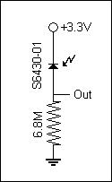
I started by simply hooking the sensors with the circuit to the right. It works fairly well for the S6400 series sensors when measuring voltage with a multimeter or oscilloscope. But for the S9702, the responsiveness was not as great and so higher resistor values were needed to amplify the signal. However, at such high resistances, it was over the input impedance of my measuring devices, so my measurements were not valid. And even if the measuring devices had a higher input impedance, the input pin of the micro controller only has a 2.5K ohm input impedance.
An interesting find from this attempt was that for sensing ambient room light, the resistor values needed to be higher for green, and even higher for blue in order to get the full voltage swing of response.
Attempt 2
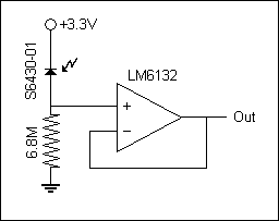
To combat the high impedance of the output, I tried to use an op-amp as a voltage follower. However, I got some strange periodic behavior in the voltage output and also some strange voltage off-set. It would read from -0.5V-ish to 2.7V-ish, a -0.5 off-set. Other more complicated circuitry were also recommended and tried by Prof. Lynch and Prof. Peshkin, but none really worked very well for me.
Attempt 3
This was the third and final attempted circuitry. I used a simple transistor to give the output roughly a 200x current gain, which allowed me to use a much smaller resistor to lower the output impedance. Although I did not look into this in great detail, it seems like there was a huge variance in the amount of current gain between individual transistors. Furthermore, different resistor values work better under different light conditions. So a trim-pot might be a better design if you plan on reproducing this circuit.
Code
Overview
The code listed here will allow the e-Puck to sync up with the MATLAB program, calibrate the sensor, start the lawn mowing sweep, and update position/heading coordinates. Sensor readings along with the location are taken every 200ms and sent back to the PC only when the e-Puck is going in a straight line. Much of the code was programmed in the same fashion as the standard library of e-Puck codes and NUtest.
Code for e-Puck
This code borrows many functions from the standard e-Puck library and other added functions by Prof. Lynch in the NUtest.c version of the e-Puck code.
// main.c for RedScan project
// James Yeung
// 6/1/2008
//
// This code is for the e-puck to be used in conjunction with RedScan.m in MATLAB.  It will control the e-Puck to set up the bluetooth
// connection with PC, calibrate the sensor, perform the lawn mowing pattern, send sensor readings to PC, and allow user update of
// position/heading coordinates.

#include <p30f6014A.h>  					// contains register definitions, etc., for the dsPIC

#include <string.h>  						// string manipulation
#include <ctype.h>   						// contains the "toupper" command to convert lower to uppercase
#include <stdio.h>   						// standard I/O routines
#include <math.h>    						// math functions like sqrt, cos, etc.

#include <a_d/advance_ad_scan/e_ad_conv.h>  			// reads the A/D channelsp
#include <a_d/advance_ad_scan/e_acc.h>	    			// reads the 3 accelerometer channels (using e_ad_conv)
#include <motor_led/e_epuck_ports.h>        			// gives mnemonic names to pins, defines simple asm functions
#include <motor_led/e_init_port.h>          			// initializes the port values and whether input or output
#include <motor_led/advance_one_timer/e_led.h>  		// uses the LED's with interrupts, to allow blinking, etc.
#include <motor_led/advance_one_timer/e_motors_NU.h>  		// interrupt-driven motor routines (step every x millisecs, e.g.)
#include <motor_led/advance_one_timer/e_agenda_NU.h>  		// manages "agenda" (the interrupt routines)
#include <uart/e_uart_char.h>               			// uses the uarts for comm (in this case, bluetooth with PC)

#define uart_send_static_text(msg) do { e_send_uart1_char(msg,sizeof(msg)-1); while(e_uart1_sending()); } while(0)
#define uart_send_text(msg) do { e_send_uart1_char(msg,strlen(msg)); while(e_uart1_sending()); } while(0)
#define SENSOR_OFFSET 4.5

static char buffer[52*39*2+3+80];
int i;
char c='z';
float x,y,theta,dist,heading,diff,x_target,y_target,theta_target,speed,j;

// return the angle limited to [-PI, PI]; PI defined in e_motors_NU.h
float anglelimit(float ang) {
  while (ang<-PI) ang += 2.0*PI;
  while (ang>PI) ang -= 2.0*PI;
  return ang;
}

void go_to(float x_target, float y_target, float theta_target){
	theta_target = anglelimit(theta_target*DEG2RAD);
	e_get_configuration(&x,&y,&theta);
	dist = sqrt((x-x_target)*(x-x_target)+(y-y_target)*(y-y_target));
	if (dist>0.1) {  // don't do the first rotate and translate if goal is too close
		heading = atan2(y_target-y,x_target-x);
		diff = anglelimit(heading-theta);
		if (diff<(-0.5*PI)) {
			dist = -dist;
			diff = diff+PI;
		}
		else if (diff>(0.5*PI)) {
			dist = -dist;
			diff = diff-PI;
		}
		speed = e_rotate(diff,2.0);     		// rotate at 2 radians/sec
		while((e_get_goal_active_left()!=0) || (e_get_goal_active_right()!=0));
		theta = theta + diff;
		speed = e_translate(dist,4.0);  		// translate at 4 cm/sec (max around 12.9 cm/sec)
		while((e_get_goal_active_left()!=0) || (e_get_goal_active_right()!=0));
	}
	diff = anglelimit(theta_target - theta);
	if (abs(diff)>0.02) {             			// don't do final rotate if already close to desired angle
		speed = e_rotate(diff,2.0);     		// rotate at 2 radians/sec
		while((e_get_goal_active_left()!=0) || (e_get_goal_active_right()!=0));
	}
}

void read_incoming(void){
	int flag=0;
	while (e_getchar_uart1(&c)==0 || flag == 0){     	// function in uart/e_uart_char.h
		if(c>0){
			flag = 1;
		}
	}
	buffer[0]=c;
	i = 1;
	do if (e_getchar_uart1(&c))   				// "do" put chars in string while chars available
		buffer[i++]=c;
	while (c!='z');   					// end "do" when char is newline or return
	buffer[i++]='\0';					// end the string
}

void wait4confirm(void){
	c = 'z';
	while (c!='A'){
		e_getchar_uart1(&c);
	}
	c = 'z';
}

void send_reading(void){
	e_get_configuration(&x,&y,&theta);
	sprintf(buffer,"%fz%fz%dz",x,y,e_get_acc(0));
	uart_send_text(buffer);
}

int main(void){
	e_init_port();						// configure port pins
	e_start_agendas_processing();				// start the motor interrupt service routines
	e_init_motors();
	e_init_uart1();
	e_init_ad_scan(ALL_ADC);
	e_set_agenda_cycle(send_reading, 200);			// setup send_reading agenda in interrupt

	uart_send_static_text("Az");				// send confirmation for communication link

	wait4confirm();
	e_acc_calibr();						// calibrate sensor for black

	wait4confirm();
	sprintf(buffer,"%dz",e_get_acc(0));
	uart_send_text(buffer);					// calibrate sensor for white

	wait4confirm();
	e_set_configuration(0.0,0.0,0.0);			// calibrate e-puck's location/heading to (0,0,0)

	e_activate_agenda(send_reading, 200);			// start send_reading agenda in interrupt
	e_pause_agenda(send_reading);				// pause send_reading agenda in interrupt

	j=0;
	for(i=0;i<25;i++){
		e_restart_agenda(send_reading);			// start send_reading agenda in interrupt
		go_to(50.0,j+0.0,0.0);
		e_pause_agenda(send_reading);			// pause send_reading agenda in interrupt
		uart_send_static_text("Az");			// send confirmation for image update
		go_to(50.0,j+1.0,0.0);
		e_restart_agenda(send_reading);
		go_to(0.0,j+1.0,0.0);
		e_pause_agenda(send_reading);
		uart_send_static_text("Az");			// send confirmation for image update
		go_to(0.0,j+2.0,0.0);

		e_get_configuration(&x,&y,&theta);		// send pos/heading info
		sprintf(buffer,"%fz%fz%fz",x,y,theta*RAD2DEG);
		uart_send_text(buffer);

		read_incoming();				// wait for pos/heading update

		sscanf(buffer,"(%f,%f,%f)z",&x,&y,&theta);	// update pos/heading info
		e_set_configuration(x,y,theta*DEG2RAD);
		j=j+2.0;
	}
	return 1;
}
Code for MATLAB
RedScan.m
The main script that starts the connection and interface.
%  RedScan.m  James Yeung 6/1/2008
%  This program is designed to communicate to an e-puck via blutooth using RS232 protocol.
%  red_scan.hex will have to be on the e-puck for this to work properly.
%
%  The main loop of this program waits for a character input from the user,
%  upon which it transmits the ascii value and waits for data to be written.

output_file = fopen('output.txt','w');

image = zeros(500, 500, 3);

s = serial('COM6','BAUD',19200);            % Create serial object (PORT Dependent)
fopen(s);                                    % Open the serial port for r/w

inNum(64) = 0;
outChar = 'a';
ii = 0;

input('Restart e-puck and press enter.');

ReadNum;
if(inNum(1) == 65)
    fprintf('Communication link ready.\n');
else
    fprintf('Error: Restart e-puck and MATLAB program.\n');
end

input('Place e-puck in dark spot for calibration. Press enter when ready.');
fprintf(s,'%c','A');
input('Place e-puck in bright spot for calibration. Press enter when ready.');
fprintf(s,'%c','A');
ReadNum;
max_val = temp;
fprintf('Max value: %d',temp);
fprintf('\n');
input('Place e-puck in location/heading (0,0,0). Press enter when ready.');
imshow(image);
fprintf(s,'%c','A');

for iii = 1:25
    for jjj = 1:2
        ReadNum;
        while(inNum(1) ~= 65)
            x = round(temp*10);
            ReadNum;
            y = round(temp*10);
            ReadNum;
            image(500-y+1:500-y+10,x+1:x+5,1) = temp/max_val;
            ReadNum;
        end
        inNum(1) = 66;
        imshow(image);
    end
    UpdatePos;
end

outChar = input('Type "A" to get value, "Q" to quit: ','s');
while(outChar ~= 'Q')
    fprintf(s,'%c',outChar);
    ReadNum;
    fprintf('Current value: %d\n',temp);
    outChar = input('Type "A" to get value, "Q" to quit: ','s');
end


% myChar = 'a';
% prompt = 'Enter a character (q to exit): ';
%
% while (myChar ~= 'q')                       % While user hasn't typed 'q'
%     fprintf(s, '%s', myChar(1))             % Write first char of user input to serial port
%     fprintf(fscanf(s))                      % Read Data back from PIC
%     myChar = input(prompt, 's');            % Get user input
% end

fclose(output_file);
fprintf('Closing communication link...\n');
fclose(s);                                  % Close the serial port
fprintf('Communication link closed.\n');
fprintf('Deleting communication link...\n');
delete(s);                                  % Delete the serial object
fprintf('Communication link deleted.\n');
fprintf('Program terminated.\n');
ReadNum.m
A sub routine to read from incoming RS232 stream. Stores individual incoming characters in "inNum(ii)" and the final number in "temp".
ii = 1;
inNum(ii) = fread(s,1);
while(inNum(ii) ~= 122)
    ii = ii + 1;
    inNum(ii) = fread(s,1);
end

ii = 1;
while(inNum(ii) ~= 0)
    buffer(ii) = cast(inNum(ii),'char');
    ii = ii + 1;
end

temp = sscanf(buffer,'%f',1);
UpdatePos.m
A sub routine to ask user to manually input position/heading coordinates to update the e-Puck.
fprintf('e-puck thinks its position/heading is (');
ReadNum;
fprintf('%f,',temp);
ReadNum;
fprintf('%f,',temp);
ReadNum;
fprintf('%f)\n',temp);
outChar = input('Enter real position/heading (x,y,theta): ','s');
fprintf(s,'%c',outChar);
fprintf(s,'%c','z');
ErrorPlot.m
A routine that is called at the end of the program to plot the error between captured image and theoretical image.
real_image = zeros(500,500,3);
for x = 1:500
    for y = 1:500
        real_image(y,x,1) = 1 - sqrt(abs(250-x)^2+abs(250-y)^2)/300;
    end
end

error_image = zeros(500,500);
for x = 1:500
    for y = 1:500
        error_image(x,y) = image(y,x,1) - real_image(y,x,1);
    end
end

[x,y]=meshgrid(1:500,1:500);
surf(x,y,error_image,'EdgeColor','none')
Results
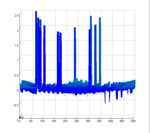
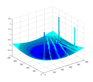
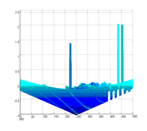
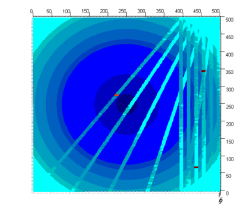
The 3D error plots give you the percentage error for each of the points of the captured image compared to the projected image. Ideally, the graph would be flat with the z-intercept at 0. A negative z value indicates a lower than expected value for that coordinate.
The first trial run covered the entire image. The spikes are a glitch that happens when collecting readings. I'm not exactly sure why there are spikes. I also forgot to capture the reproduced image of the first full trial run. In this run, I simply allowed the e-Puck to perform the full lawn mowing pattern to cover the entire image. Initially, I tried to simply feed the e-puck with updated coordinates, but it didn't seem to work very well because each time it would get more and more off course. So I decided to manually move the e-Puck to the correct each time it asked me to update its position coordinates.
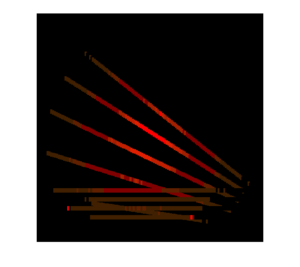
The second trial run demonstrates the e-Puck's ability to adjust to manual movement of the e-Puck. When the e-Puck prompts for an update for its position coordinates, I would move the e-Puck to a dramatically different position and give it the coordinates at which I put it at. As you can see from the plots, the diagonal lines are the new path that the e-Puck chose to take due to that movement.
Possible Future Improvements
- To allow the user to manually input a path for the e-Puck to explore.
