Difference between revisions of "Driving using a single MOSFET"
| Line 4: | Line 4: | ||
Most practical is to turn on/off a MOSFET. MOSFETs in their open state may have a resistance of 10^12 ohms, while in their closed state as little as 0.01 ohm - a remarkable dynamic range. Further, they are turned on by a "gate voltage" with essentially no current required. There is some gate capacitance, typically 5nF, but this won't require much current except at very high switching rates. |
Most practical is to turn on/off a MOSFET. MOSFETs in their open state may have a resistance of 10^12 ohms, while in their closed state as little as 0.01 ohm - a remarkable dynamic range. Further, they are turned on by a "gate voltage" with essentially no current required. There is some gate capacitance, typically 5nF, but this won't require much current except at very high switching rates. |
||
| ⚫ | |||
MOSFETs have three terminals, called Drain, Source, and Gate. If you are familiar with bipolar transisitors, an N-channel enhancement-mode MOSFET may be compared to an NPN transistor, where Drain-Source-Gate of the MOSFET are Collector-Emitter-Base of the NPN respectively. |
MOSFETs have three terminals, called Drain, Source, and Gate. If you are familiar with bipolar transisitors, an N-channel enhancement-mode MOSFET may be compared to an NPN transistor, where Drain-Source-Gate of the MOSFET are Collector-Emitter-Base of the NPN respectively. |
||
We'll use a MOSFET with the Source grounded, the Drain connected (through a load) to a positive supply voltage, and a logic level input to the Gate, which will turn the Source-Drain connection on/off. |
We'll use a MOSFET with the Source grounded, the Drain connected (through a load) to a positive supply voltage, and a logic level input to the Gate, which will turn the Source-Drain connection on/off. |
||
| ⚫ | |||
| ⚫ | |||
MOSFET specifications indicate an "on voltage" applied to the Gate (with respect to Source), required to turn the Source-Drain connection on. The higher the Gate voltage, the lower the resistance of the Source-Drain connection. Graphs show the dependence of Drain-Source current on Drain-Source voltage and Gate-Source voltage. Often these are called just Drain current, Drain voltage, and Gate voltage. |
MOSFET specifications indicate an "on voltage" applied to the Gate (with respect to Source), required to turn the Source-Drain connection on. The higher the Gate voltage, the lower the resistance of the Source-Drain connection. Graphs show the dependence of Drain-Source current on Drain-Source voltage and Gate-Source voltage. Often these are called just Drain current, Drain voltage, and Gate voltage. |
||
For many MOSFETs, turning them on fully requires 7 to 10 volts a the Gate -- which is more than logic levels can supply. The IRFU3708 is nice in that it requires relatively low Gate voltages, and conducts high Drain currents. (see graph) |
For many MOSFETs, turning them on fully requires 7 to 10 volts a the Gate -- which is more than logic levels can supply. The IRFU3708 is nice in that it requires relatively low Gate voltages, and conducts high Drain currents. (see graph) |
||
| ⚫ | |||
The circuit diagram shows how to use the IRFU3708 to control a high-current load, such as a solenoid or a brushed DC motor. Note that the logic level output is 0 or +5 volts, but the +V applied to the load can be much higher than that; you can control +24v applied to the load for instance. |
The circuit diagram shows how to use the IRFU3708 to control a high-current load, such as a solenoid or a brushed DC motor. Note that the logic level output is 0 or +5 volts, but the +V applied to the load can be much higher than that; you can control +24v applied to the load for instance. |
||
Revision as of 19:35, 26 December 2006
Logic-level outputs (such as the IO pins of a Basic STAMP or a PIC chip) have nowhere near enough current capacity to drive a motor directly. Typically they can source (connect to +5v) or sink (ground) up to 20mA without damage. You need to be able to use the logic-level output voltage (0v or 5v) to turn on/off a device that can handle 100mA of current, or more, up to 30A, depending on the motor being controlled.
There are many ways to do this. Conceptually simplest is to drive the coil of a relay; some relays can be closed by 5V at 40mA or less. (The coil resistance would have to be 125 ohms or more.) Even 40mA is too much for many chips though.
Most practical is to turn on/off a MOSFET. MOSFETs in their open state may have a resistance of 10^12 ohms, while in their closed state as little as 0.01 ohm - a remarkable dynamic range. Further, they are turned on by a "gate voltage" with essentially no current required. There is some gate capacitance, typically 5nF, but this won't require much current except at very high switching rates.
MOSFETs have three terminals, called Drain, Source, and Gate. If you are familiar with bipolar transisitors, an N-channel enhancement-mode MOSFET may be compared to an NPN transistor, where Drain-Source-Gate of the MOSFET are Collector-Emitter-Base of the NPN respectively.
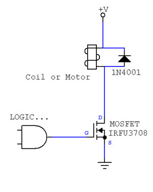
We'll use a MOSFET with the Source grounded, the Drain connected (through a load) to a positive supply voltage, and a logic level input to the Gate, which will turn the Source-Drain connection on/off.
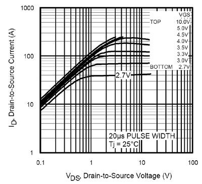
MOSFET specifications indicate an "on voltage" applied to the Gate (with respect to Source), required to turn the Source-Drain connection on. The higher the Gate voltage, the lower the resistance of the Source-Drain connection. Graphs show the dependence of Drain-Source current on Drain-Source voltage and Gate-Source voltage. Often these are called just Drain current, Drain voltage, and Gate voltage.
For many MOSFETs, turning them on fully requires 7 to 10 volts a the Gate -- which is more than logic levels can supply. The IRFU3708 is nice in that it requires relatively low Gate voltages, and conducts high Drain currents. (see graph)
The circuit diagram shows how to use the IRFU3708 to control a high-current load, such as a solenoid or a brushed DC motor. Note that the logic level output is 0 or +5 volts, but the +V applied to the load can be much higher than that; you can control +24v applied to the load for instance.
The diode is important for inductive loads such as motors, relay coils, solenoids, or electromagnets. Recall that once a current is flowing in an inductor, it has an "inertia" and will not easily stop. If the MOSFET is suddenly surned off (opened), the current flowing through the inductor will be able to continue briefly through the diode. Without the diode, the inductor could generate a high L*di/dt voltage and burn out the MOSFET.

