Driving a DC Motor using PWM
From Mech
Jump to navigationJump to searchBefore doing this exercise, read about Brushed DC Motors and Driving Using Pulse Width Modulation. In this exercise you will use a function generator to create the pulse width modulation (PWM) signal that controls the motor. This simulates a signal that could be generated by a microcontroller.
Make sure your 7.2V battery pack is charged.
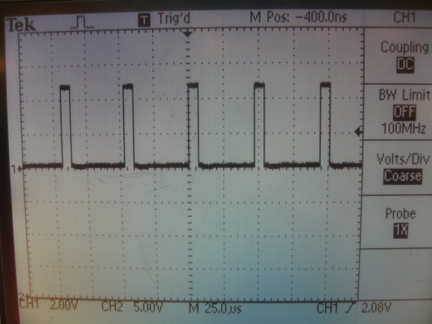
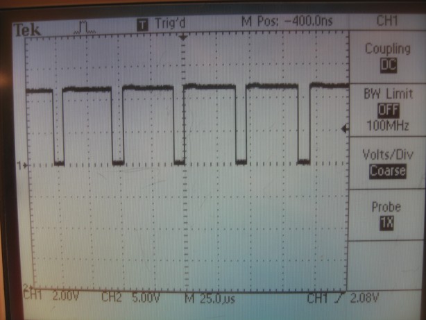
- Use a function generator to create a 20 kHz square wave between 0V (GND) and 5V. Verify that you have done this by looking at the signal on an oscilloscope. To learn how to do this with the function generator and oscilloscopes in the Mechatronics Lab, read the manuals on the Tektronix CFG253 Function Generator and Tektronix TDS220 Oscilloscope. Looking at the oscilloscope signal, vary the duty cycle (the percentage of time the signal is "high" each cycle) of the signal using the symmetry knob, say from 20% to 80%. Your oscilloscope should look something like the figures below.
- Attach your battery pack to your breadboard. Use your 7805 5V voltage regulator so that you have 5V and 7.2V (with respect to the ground pin of the voltage regulator) available for use. Verify using your multimeter or an oscilloscope. (In my case, I measured about 5.2V and 9.5V.) Make sure your function generator ground is connected to the ground pin of the voltage regulator.
- Use a 74HC04 Hex Inverter/Buffer to get an inverted version of the function generator signal, in addition to the original signal. Verify by looking at both the original signal and the inverted signal simultaneously on the oscilloscope.
- Send these two signals (original and inverted) to inputs 2 and 7 of an L293B H-bridge. Make sure this H-bridge chip is correctly powered by attaching +5V to the Vss pin (the "logic" power supply) and the battery's +7.2V to the Vs pin (the motor power supply). Don't forget to attach the ground pins too! Following Figure 9 of the data sheet showing bidirectional motor control, connect the appropriate H-bridge outputs to the two terminals of your gearmotor. Use 4 1N4001 "flyback" diodes as shown in Figure 9. Put a 0.1uF capacitor across the terminals of your motor to reduce electrical noise due to your motor. Now demonstrate that you can control the speed and direction of the motor by changing the duty cycle of your square wave signal. Make sure you understand the truth table in Figure 9.

