Difference between revisions of "Diodes and Transistors"
| Line 160: | Line 160: | ||
If <math>V_{in}</math> < 0.7V, then the current is amplified by the pnp transistor. |
If <math>V_{in}</math> < 0.7V, then the current is amplified by the pnp transistor. |
||
=====Motor Speed Controller Example (Lab 1)===== |
|||
Suppose we want to control the speed of a motor by varying the input voltage between +5V and -5V. We attempt to do this by setting put a voltage divider with a potentiometer like in the circuit below. |
|||
[[Image:speed_controller_simple.gif]]We model our motor with a simple resistor RL. If ''RL'' is infinitely large (no current flowing through), then there will be a 7.2V drop across ''R1'' and ''R'', and <math>V_{in}</math> can take a value between 4.8V and -4.8V. |
|||
For the maximum voltage case, our circuit with voltage sources looks like this: |
|||
[[Image:speed_controller_sources.gif]] We know that RL is ''not'' infinitely large because motors can draw quite a lot of current. If ''RL=0'' (short ciruict), then the <math>V_{in}=0</math>. We can expect <math>V_{in}</math> to be somewhere between 0V and 4.8V. |
|||
We can solve the circuit with the following equations: |
|||
<math>I_1=I_2+I_3</math> &nsb;&nsb;&nsb;(KCL) |
|||
Revision as of 11:51, 22 June 2006
Diodes
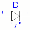
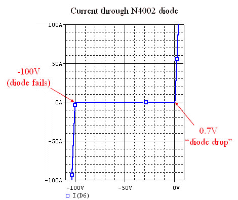
We can take advantage of the properties of a p-n junction to make a diode, which is an electrical component that only allows current flow in one direction. A diode made of silicon needs about 0.7V across it in order to conduct. At about -100V, the diode will fail and the current will force its way though. This is know as diode breakdown.
Applications of Diodes
Half-Wave Rectifier
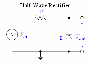
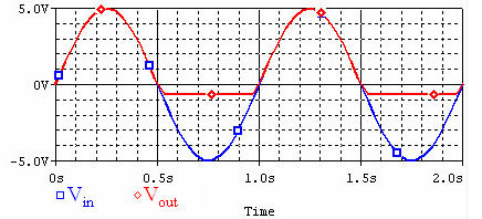
A half-wave rectifier will cut off half of a sine wave, leaving only the positive or negative side.
The schematic for a simple rectifier:
The graph for half-wave rectifier:
Flyback Diode
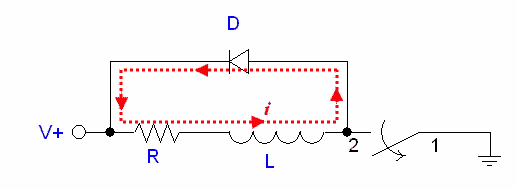
An approximate model of a DC motor is a resistor and inductor in series. If we suddenly break the circuit to switch off the motor, the inductor will continue to try and push current though, resulting in a sudden spike in voltage (), damaging the switch or other electrical components. Mechanically, this is like trying to bring the velocity of a certain moving mass to zero, instantly. We can solve this problem by adding a diode, as shown:
This way, the current can flow through the diode and dissipate in the resistor. Yet, the diode prevents a short circuit from occurring when the switch is closed.
Peak Detector
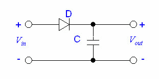
We can make a peak detector if we hook up our circuit like this:
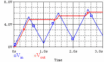
The graph of the input and output voltages looks like this:
Each time the input voltage dips, the diode prevents the capacitor from draining.
There are two problems with this circuit: First, the voltage of the peak must be greater than the voltage drop, or we won't detect anything. Second, the circuit has a very low impedance, and the capacitor drains a lot of current. A better peak detector can be built with op-amps.
Voltage Clamp
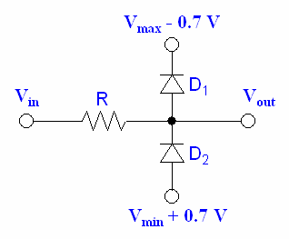
A voltage clamp will limit the output voltage, which is useful when we need to protect circuits from high voltages.
In this ciruit, if exceeds , the diode will conduct and force the voltage to stay at . At lower voltages, the diode does not conduct, and the voltage is not affected.
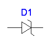
Zener Diodes
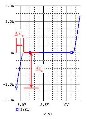
Zener diodes have a low breakdown voltage, or zener voltage, and can allow reverse current to flow without being destroyed. A good zener diode can also maintain a fairly constant voltage over a large range of currents. The voltage-current graph of a zener diode looks like this:
Voltage Regulator
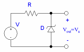
We can use a zener diode to build a voltage regulator like this:
is the reverse breakdown or zener voltage.
Even if the current through the diode fluctuates, the voltage will remain fairly stable. Choose a resistance R large enough such that the power specs of the zener diode are not exceeded, but not so large that it limits our current too much.
For example, if our diode has a zener voltage of 5V and can handle 1W, and our voltage source has a maximum voltage of 20V:
The largest amount of current our diode will ever have to handle is the current through the diode when there is no external load. Therefore:
This means that we need at least 75Ω to protect our diode. Keep in mind that we must meet the power ratings for our resistor as well.
Because current is flowing through the resistor and diode even when there is no load, power is being wasted. We can do better with voltage regulator chips like a 7805 chip (78xx for xx volts).
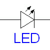
LEDs (Light Emitting Diode)
And LED is a type of diode that emits visible or infrared light proportional to the current passing through it (up to a maximum before it burns out).
Bipolar Junction Transistors (BJT)
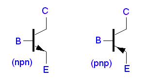
There are two types of of BJTs; n-p-n and p-n-p:
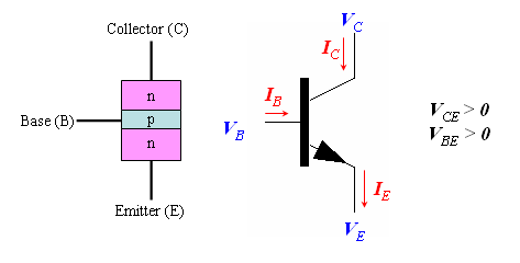
npn
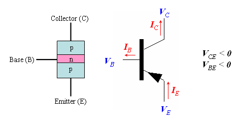
pnp
For the transistors, we have the following relationship for the voltages and curents:
Under normal operation, BE is forward biased, and CB is reverse biased.
BJTs have three regions of operation:
Cutoff: (no collector current)
Active: β (collector current is proportional to base current by factor β)
Saturated: ≈ (for npn); (maximum collector current)
Applications of BJTs
Common Emitter Amplifier Circuit
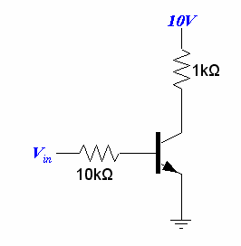
In a common emitter circuit, the emitter of a transistor is grounded and an input voltage is applied at the base. An example common emitter circuit with a transistor (β=100) is drawn below:
If < 0.7V (same as the diode drop), the p-n junction is not forward biased and no will equal 0.
If > 0.7V, then
β
Now we will try to calculate how large has to be to saturate the transistor. When , the transistor becomes saturated. If the drop across the collector and emitter of the transistor is equal to 0.2V, then the drop across the resistor at the collector must equal 9.8V. Thus:
β
Then we find :
Ω
or greater.
cutoff: < 0.7V
active:0.7V < <1.68V
saturated:1.68V <
If we are using the transistor as a switch, we should fully saturate it to save power and reduce heat.
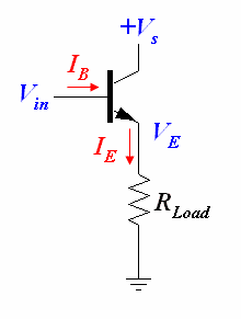
Emitter Follower
The emitter follower is a very simple current amplifier, taking advantage of the fact that β. The high input impedance means that our imput signal does not need to work as hard.
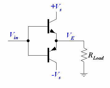
Push-Pull Follower
If we put two emitter followers together (npn transistor for positive voltages; pnp transistor for negative voltages), we get a push-pull follower.
If > 0.7V, then the current is amplified by the npn transistor.
If < 0.7V, then the current is amplified by the pnp transistor.
Motor Speed Controller Example (Lab 1)
Suppose we want to control the speed of a motor by varying the input voltage between +5V and -5V. We attempt to do this by setting put a voltage divider with a potentiometer like in the circuit below.
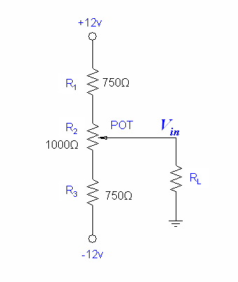 We model our motor with a simple resistor RL. If RL is infinitely large (no current flowing through), then there will be a 7.2V drop across R1 and R, and can take a value between 4.8V and -4.8V.
For the maximum voltage case, our circuit with voltage sources looks like this:
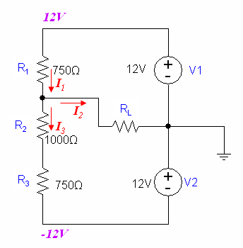 We know that RL is not infinitely large because motors can draw quite a lot of current. If RL=0 (short ciruict), then the . We can expect to be somewhere between 0V and 4.8V.
We can solve the circuit with the following equations:
&nsb;&nsb;&nsb;(KCL)
