Difference between revisions of "Design and Control of a Pantograph Robot"
Ben Tollberg (talk | contribs) |
Ben Tollberg (talk | contribs) |
||
| Line 99: | Line 99: | ||
=PIC Code= |
=PIC Code= |
||
=Operating Instructions= |
=Operating Instructions= |
||
The steps to operate the robot arm in its current configuration are as follows: |
|||
'''1. Plug in and check all connections.''' Connect the power USB cord for the PIC and the RS-232 cable to the laptop that will be running the MATLAB program. Plug in the power supply for the motors. Check to make sure that the motor leads are connected to the H-bridge amplifiers and the DB9 encoder cables are plugged in. |
|||
'''2. Run the MATLAB program.''' Open MATLAB and run the me333gui.m file contained in the folder located in the MATLAB Code section of this page. This will open the GUI interface that sends commands to the robot arm. You may have to choose "Add to path" if a window pops up telling you that the folder containing the M-file is not in the predefined path. |
|||
'''3. Connect to the COM port.''' There is a box in the GUI that says "COM#". Replace the # sign with the number of the serial port that the RS-232 cable is connected to and press connect. If you select an unavailable port an error message will appear in the main MATLAB command window. |
|||
=Next Steps= |
=Next Steps= |
||
Revision as of 12:41, 8 June 2010
Overview
The goal of this project was to design and build a 2-DOF Pantograph Robot. The user would be able to specify and X and Y location for the end point of the pantograph, along with different paths that the robot arm could take. The basic circuit design and computer code was taken from the High Speed Motor Control project and adapted to work with our robot design.
Kinematics
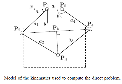
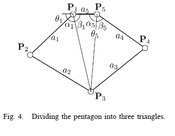
The kinematics for our robot design were derived from The Pantograph Mk. II - A Haptic Instrument. The forward and inverse kinematics as used in the MATLAB program are shown below, along with diagrams from the paper showing how the reference frames are defined in our setup. These angles are all calculated in radians, other parts of the programs convert this to degrees for graphing and user interfaces. The full programs can be found in the zip files below.
Forward Kinematics
x2 = L1 * cos(theta);
y2 = L1 * sin(theta);

y4 = L4 * sin(alpha);
x4 = L4 * cos(alpha) - L5;

two_to_four = sqrt((x2-x4).^2 + (y2-y4).^2);

two_to_h = (L2^2 - L3^2 + two_to_four.^2) ./ (2 * two_to_four);

yh = y2 + (two_to_h./two_to_four).*(y4-y2);
xh = x2 + (two_to_h./two_to_four).*(x4-x2);

three_to_h = sqrt(L2^2 - two_to_h.^2);

x3 = xh + (three_to_h./two_to_four) .* (y4-y2);
y3 = yh - (three_to_h./two_to_four) .* (x4-x2);
Inverse Kinematics
L13 = sqrt(x3.^2+y3.^2);
L53 = sqrt((x3+L5).^2 + y3.^2);

alphaOne = acos((L1.^2 + L13.^2 - L2.^2)./(2.*L1.*L13));
betaOne = atan2(y3,-x3);
thetaOne = pi - alphaOne - betaOne;

alphaFive = atan2(y3,x3+L5);
betaFive = acos((L53.^2 + L4.^2 - L3.^2)./(2.*L53.*L4));
thetaFive = alphaFive + betaFive;
Mechanical Design
Circuit Design
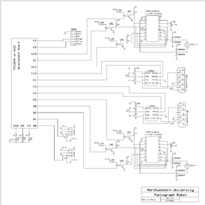
The complete circuit schematic for the current robot setup is displayed to the right. A brief description of the components in the circuit and what they do follows.
This is essentially one smaller circuit repeated for the second motor. Each motor is powered by an L298N H-bridge amplifier which is powered by 12 volts currently. These amplifiers are capable of sending out four different signals, however in this application the matching inputs and outputs are connected in parallel in order to increase the available current.
The PIC sends three signals to each H-bridge, one for each motor lead and an enable signal that activates the amplifier. These signals pass through 4N27 optoisolators to shield the motors from signal noise.
Each motor encoder is connected to an LS7083 encoder counter chip to allow the PIC to keep track of the motor angle in order to control the position of the end effector. This connection is made through a DB9 connector that interfaces with the plug attached to each motor.
There are two hall effect sensors that are mounted on the robot base and connected to the PIC. These allow the user to set the position of the arms by manually moving them at the beginning of the program until they are tripped by small magnets mounted on the robot arms.
The PC communicates with the PIC via RS232 using a MATLAB program. This allows the robot arm to be completely controlled by a PC once the program is loaded onto the PIC chip.
Parts List
| Electrical Components Needed. | Quantity | Data Sheets |
|---|---|---|
| PIC 32 on NU32 board | 1 | Introduction to the PIC32 |
| H-bridges L298 | 2 | data sheet |
| Optoisolators 4N27 | 6 | data sheet |
| Quadrature Up/Down decoders LS7083 | 2 | data sheet |
| Hall Effect Sensors | 2 | Hall Effect Sensor |
| 35V 9A Schottkey Diodes 90SQ035-ND | 8 | data sheet |
| Harmonic Drive RH-8D-3006 Actuator with 100:1 gear ratio and 1000 count per revolution encoder | 2 | data sheet |
| Power Supply | 1 | N/A |
MATLAB Code
PIC Code
Operating Instructions
The steps to operate the robot arm in its current configuration are as follows:
1. Plug in and check all connections. Connect the power USB cord for the PIC and the RS-232 cable to the laptop that will be running the MATLAB program. Plug in the power supply for the motors. Check to make sure that the motor leads are connected to the H-bridge amplifiers and the DB9 encoder cables are plugged in.
2. Run the MATLAB program. Open MATLAB and run the me333gui.m file contained in the folder located in the MATLAB Code section of this page. This will open the GUI interface that sends commands to the robot arm. You may have to choose "Add to path" if a window pops up telling you that the folder containing the M-file is not in the predefined path.
3. Connect to the COM port. There is a box in the GUI that says "COM#". Replace the # sign with the number of the serial port that the RS-232 cable is connected to and press connect. If you select an unavailable port an error message will appear in the main MATLAB command window.


