Comparators
A comparator subtracts two voltages and gives you a logic output. Thus it lives at the boundary between the analog world of continuous voltages, and the digital world of 1's and 0's, represented by +5V and 0V, logic high and logic low.
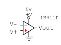
Comparators have two inputs, called inverting and non-inverting inputs, and labeled simply - and + on a circuit diagram. We will call the potential at these inputs V-- and V+. Don't confuse these inputs with power supply connections! See figure 1: inputs on the side, power on the top and bottom. Often power is not even shown, but if you neglect to provide it the chip won't work.
The output of a comparator is logic high (+5V) if V+ > V-- and low (0V) if V+ < V-- . If they are within about 1mV of equal, anything goes.
Comparators are much like opamps, but opamps intend to have a continuous output Vout = G(V+ - V--), where comparators intend to saturate, that is, always to have a full positive or zero output.
An ideal comparator, like an ideal opamp, has infinite input impedance. That means that it observes the voltage at its input while allowing no current to flow. Real comparators are pretty close to this ideal, swallowing only a few nA. This is very useful when you have a high impedance signal (having very little current available) such as a phototransistor.
An ideal comparator, like an ideal opamp, has zero output impedance. That means, when it drives its output to 0V, it will maintain 0V regardless of how much current it has to sink in order to do so. Real comparators are pretty good -- if forced to sink too much current they may burn up, but the output voltage won't rise more than 100mV or so.
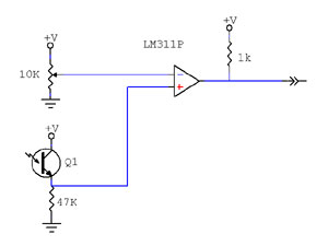
We will focus on the LM311P, a particularly nice comparator. Look up its datasheet. In the application shown, it is performing as a thresholding detector for a phototransistor. The trimmer potentiometer sets V- to an adjustable potential between 0V and 5V. If the phototransistor receives enough light and conducts enough current to bring V+ above the potential of V-, the output of the comparator goes high.
The LM311P, like most comparators, is open-collector. That means it is capable of grounding its output to indicate logic low, but that's all it can do. It cannot drive its output high (to +5V for instance). All it can do to indicate logic high output is NOT ground its output. It's your job to pull the output high (with a "pull up resistor") and the LM311P will pull it low when it needs to.
Why don't they include a pull up resistor inside? Sometimes they do. However, the open collector output allows you to pull it up to other voltages besides +5 at your whim, for instance to +3 or +24, or to drive an LED (and its limiting resisitor.) You can also arrange several comparators "wired OR", meaning the outputs of several comparators are connected and if any of them pulls the output to ground, it dominates all the others. You couldn't do that if one was pulling the output high and another pulling it low.
There are several limitations, but comparators are nevertheless very easy, robust, useful components.
- Comparators are limited in amount of current they can sink (sink means take to ground.) They can overheat and die. This one can sink 50mA -- a lot by comparator standards.
- Comparators are limited in the pull-up voltage they can withstand. This one can withstand +50V (positive only, mind you!) That's also huge.
- LM311P has several connections you didn't want to know about: strobe, balance, and emitter. Tie strobe and balance to Vcc+ (the positive supply) and the emitter to Vcc- (which is usually ground)
- LM311 runs happily with Vcc+ = 5V and Vcc- = 0V. There are many other ways to use it
- LM311 allows its inputs to range independently anywhere from +15 to -15, without damage. Many comparators are much more finicky. For many, the range of the inputs must not exceed the range between the power supply rails (e.g. 0 to +5)
Comparators with Hysteresis
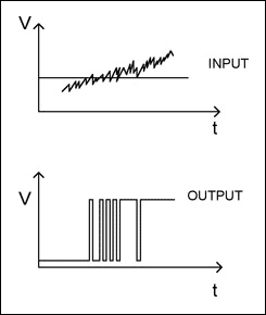
You may run into a problem with implementing a comparator circuit as described above if your input signal has any noise in it, especially in the anything goes region where the two inputs (inverting and non-inverting) are nearly equal. The noise in the signal could cause the comparator output to flicker, as shown on the right. In order to eliminate this flickering behavior, a hysteresis band can be added to the comparator.
A comparator with hysteresis has two important thresholds: upper and lower. Unlike a simple comparator, however, the output of the comparator doesn't depend solely on whether the input is above or below one of these thresholds. It depends on both the current state of the output and the current value of the input. If the output is high, it will stay high until the input voltage drops below the lower threshold. If the output is low, it will stay low until the input voltage rises above the upper threshold.
A common example of a hysteresis band is the thermostat in your house. If the system is cooling, it will cool the house down to a given temperature and then turn off. It will not turn on until the room has heated up a certain amount again, otherwise it would be turning off and on quite rapidly. This difference in temperatures allowed before the cooling turns back on is a hysteresis band. If the system is currently on, the high output, it will stay on until the temperature is below a lower threshold. If the system is off, the low output, it will stay off until the temperature is above an upper threshold.
In order to implement this electronically, we can use a comparator as shown in the circuit diagram below. This circuit creates a noninverting comparator with hysteresis.
The important equations for setting the thresholds of the hysteresis band are as follows:
where is the upper threshold and is the lower threshold of the hysteresis band. The output of this circuit is shown below for a given input.


