Common xPC Blocks
The xPC blocks are found by opening up simulink and expanding the "xPC Target" menu to the left. It looks like this:

Below you will find a list of commonly used blocks and those used specifically with the Sensoray 526 data aquisition board. The pictures will show how they could be used in common applications.
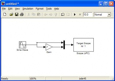
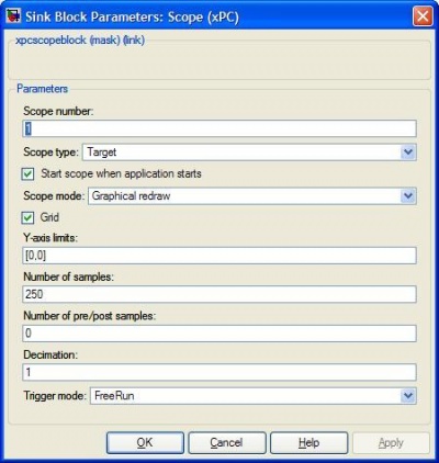
xPC Target \ Misc. \ Scope (xPC)
The target scopes are used to display data on the xPC screen. This requires the target PC to be connected to a monitor. These scopes can either plot data over time or display numerical values. Signals can be muxed to display on the same scope or multiple scopes can be used. The scope shown below will show two sin waves (one inverted).
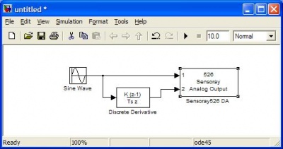
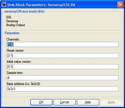
xPC Target \ D/A \ Sensoray \ Sensoray526 DA
This block is used to output analog signals on the Analog Out pins. You cannot mux signals to this block. You must specify which pins you are using in the Block Parameters and connect the individual signals, as shown below.
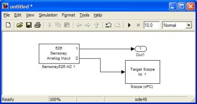
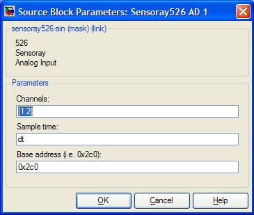
xPC Target \ A/D \ Sensoray \ Sensoray526 AD 1
This block is used to read values from the Analog-IN pins on the Sensoray board. The pins have to be individually specified, as shown below.
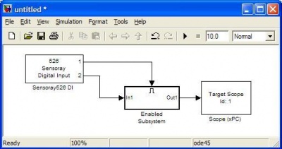
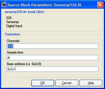
xPC Target \ Digital Input \ Sensoray \ Sensoray526 DI
This block returns High (1) or Low (0) depending on the status of the defined pins. The block below shows how port one enabling the display of pin 2 on a Target Scope.
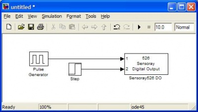
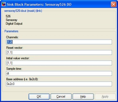
xPC Target \ Digital Output \ Sensoray \ Sensoray526 DO
This block outputs High (1) or Low (0) to the defined Digital Out pins. You must specify the initial values and reset values of these pins. NOTE: If you are using the BoB, you will need to set the initial and reset values to 1's because the pins are inverted (refer to the hardware documentation)
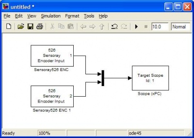
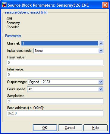
xPC Target \ Incremental Encoder \ Sensoray \ Sensoray526 ENC
This block outputs the counts from an incremental encoder. The encoder starts counting from a specified value (usually zero). You have to use a separate block for each encoder, specifying the channel for each.
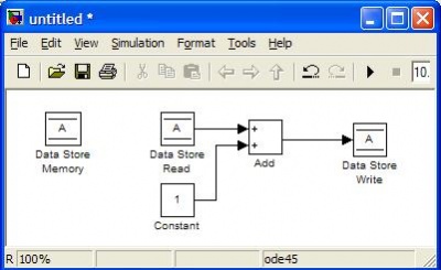
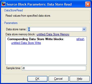
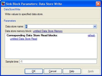
Simulink \ Signal Routing \ Data Store (Memory, Read, Write)
These blocks are used to store values in local memory during execution. This is especially useful for storing states over each timestep, such as position or heading. You must use the Data Store Memory block to define a variable name and reserve a place for it in the memory. You can then change the value using the Data Store Write block and read the value back using the Data Store Read block. For the Read/Write blocks, you must edit the Parameters to specify the name of the variable. The model below will create a variable called "A" and will add 1 to it (starts from zero) each timestep.

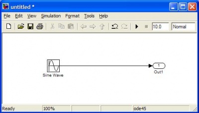
Simulink \ Sinks \ Out1
You can use this block in an xPC model to record data. This data is available after execution has finished by reading tg.OutputLog. You can mux signals into this block and tg.OutputLog will be a matrix instead of an array.