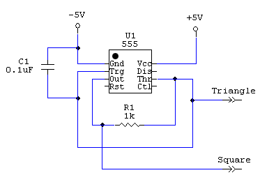
Circuit diagram for wave generator
From Mech
Jump to navigationJump to searchThe circuit shown produces a pretty good square wave (10 V peak-to-peak) able to drive a low impedance load, and a slightly curved triangle wave of lower amplitude, and only able to drive a high impednace load.
The 555 "timer" chip in the figure is shown with its pins in the actual DIP8 layout (pin 1 is upper left)
