Difference between revisions of "Choosing a Motor and Gearing Combination"
| Line 28: | Line 28: | ||
</center> |
</center> |
||
We see that the output power <math>P_{out}</math> equals the input power P_{in} |
We see that the output power <math>P_{out}</math> equals the input power <math>P_{in}</math>: |
||
P_{out} = \tau_{out} \omega_{out} = G \tau_{in} \frac{\omega_{in}}{G} = |
<math>P_{out} = \tau_{out} \omega_{out} = G \tau_{in} \frac{\omega_{in}}{G} = |
||
\tau_{in} \omega_{in} = P_{in} |
\tau_{in} \omega_{in} = P_{in}</math> |
||
since the ideal gearbox neither adds nor subtracts power. |
since the ideal gearbox neither adds nor subtracts power. |
||
| Line 38: | Line 38: | ||
reducing the maximum speed and increasing the maximum torque. The figure |
reducing the maximum speed and increasing the maximum torque. The figure |
||
below shows a speed-torque curve of a motor, and for the same motor with |
below shows a speed-torque curve of a motor, and for the same motor with |
||
gearboxes of G=2 and G=4. Also shown is a desired speed+torque |
gearboxes of <math>G=2</math> and <math>G=4</math>. Also shown is a desired speed+torque |
||
operating point for |
operating point for |
||
the motor+gearbox combination, showing that only the G=4 gearbox meets |
the motor+gearbox combination, showing that only the <math>G=4</math> gearbox meets |
||
our specification. |
our specification. |
||
[[image:gear-speed-torque.jpg|center]] |
|||
If we have two gearboxes with gear ratios G_1 and G_2, and the output |
If we have two gearboxes with gear ratios <math>G_1</math> and <math>G_2</math>, and the output |
||
shaft of gearbox 1 is connected to the input shaft of gearbox 2, the |
shaft of gearbox 1 is connected to the input shaft of gearbox 2, the |
||
total gear ratio from the input of gearbox 1 to the output of gearbox 2 |
total gear ratio from the input of gearbox 1 to the output of gearbox 2 |
||
is G_{total} = G_1 G_2. |
is <math>G_{total} = G_1 G_2</math>. |
||
In practice, gearboxes are not 100% efficient at transmitting power. Some |
In practice, gearboxes are not 100% efficient at transmitting power. Some |
||
power is lost due to friction. Gearboxes usually have an associated |
power is lost due to friction. Gearboxes usually have an associated |
||
efficiency \eta, such that the torque output of the gearbox is actually |
efficiency <math>\eta</math>, such that the torque output of the gearbox is actually |
||
\tau_{out} = \eta \tau_{in}. The efficiencies of gearboxes attached |
<math>\tau_{out} = \eta \tau_{in}</math>. The efficiencies of gearboxes attached |
||
to each other is obtained by multiplying the individual efficiencies. |
to each other is obtained by multiplying the individual efficiencies. |
||
Gearboxes with large gear ratios are usually obtained by having several |
Gearboxes with large gear ratios are usually obtained by having several |
||
| Line 59: | Line 60: | ||
(if the gears are made with the same materials and precision). Below is |
(if the gears are made with the same materials and precision). Below is |
||
shown the speed-torque curve for a motor, a motor with an ideal gearbox |
shown the speed-torque curve for a motor, a motor with an ideal gearbox |
||
with G=2, and a motor with a gearbox with G=2 but an efficiency |
with <math>G=2</math>, and a motor with a gearbox with <math>G=2</math> but an efficiency |
||
\eta = 75%. |
<math>\eta = 75\%</math>. |
||
[[image:gear-efficiency.jpg|center]] |
|||
To choose a motor and gearbox appropriate for your application, |
To choose a motor and gearbox appropriate for your application, |
||
| Line 90: | Line 92: | ||
to choose a larger motor to meet this specification. |
to choose a larger motor to meet this specification. |
||
* You can further optimize your design for |
* You can further optimize your design for maximum efficiency at converting |
||
electrical power to mechanical power, to |
|||
save on electrical power for battery-powered robots. Motors usually |
save on electrical power for battery-powered robots. Motors usually |
||
are most efficient at converting electrical power to mechanical power |
are most efficient at converting electrical power to mechanical power |
||
| Line 98: | Line 101: | ||
designs. |
designs. |
||
* |
* Some of the mechanical power created by a motor goes to accelerate the rotor |
||
of the motor itself, and some of it goes to accelerate the load. To maximize |
|||
the mechanical power that goes to accelerate the load, you would choose |
|||
a gear ratio G = \sqrt{\frac{I_{load}}{I_{rotor}}. |
a gear ratio G = \sqrt{\frac{I_{load}}{I_{rotor}}. |
||
This is called inertia matching. This is only an issue for |
This is called ''inertia matching''. This is only an issue for |
||
more sophisticated designs. |
more sophisticated designs. |
||
Revision as of 07:24, 27 December 2006
For most robotics and mechatronics applications, DC motors run at speeds higher than we want and with less torque than we want. The most common solution to this problem is to attach the output shaft of the motor to a transmission that reduces speed and increases torque. The input to this transmission is attached to the output shaft of the motor, and the output of the transmission performs the lower speed, higher torque motion that we want (e.g., motion of a wheel, robot joint, etc.). The transmission could be built of belts and pulleys, gears, or other elements, and the output motion of the transmission can be rotational or linear. Here, let's consider the case of a rotational output motion where the output speed of the transmission is times slower than the input speed of the transmission (the speed of the motor shaft). Then we call G the gear ratio, and usually .
Let's refer to the transmission as a gearbox, since gearboxes are the most common way to get the speed reduction and torque increase.
If the input shaft to an ideal gearbox is turning with a speed and torque , then the output turns with a speed and torque , where
We see that the output power equals the input power :
since the ideal gearbox neither adds nor subtracts power.
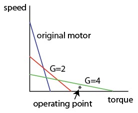
In terms of the speed-torque curve above, a gearbox has the effect of reducing the maximum speed and increasing the maximum torque. The figure below shows a speed-torque curve of a motor, and for the same motor with gearboxes of and . Also shown is a desired speed+torque operating point for the motor+gearbox combination, showing that only the gearbox meets our specification.
If we have two gearboxes with gear ratios and , and the output shaft of gearbox 1 is connected to the input shaft of gearbox 2, the total gear ratio from the input of gearbox 1 to the output of gearbox 2 is .
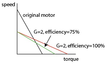
In practice, gearboxes are not 100% efficient at transmitting power. Some power is lost due to friction. Gearboxes usually have an associated efficiency , such that the torque output of the gearbox is actually . The efficiencies of gearboxes attached to each other is obtained by multiplying the individual efficiencies. Gearboxes with large gear ratios are usually obtained by having several gearing stages in series, so the total efficiency of large gear ratio gearboxes are generally lower than those with smaller gear ratios (if the gears are made with the same materials and precision). Below is shown the speed-torque curve for a motor, a motor with an ideal gearbox with , and a motor with a gearbox with but an efficiency .
To choose a motor and gearbox appropriate for your application, consider the following issues:
- What is the typical power you need? In other words, what is a
typical speed and torque operating point for your system? Choose a motor that is capable of providing this much mechanical power. (Most motors are classified according to their power.) Usually you will choose the smallest, lightest, most inexpensive motor that meets your specifications. You may also have constraints on the nominal voltage of the motor (e.g., you have a 12V supply available, so you want the motor to run at around 12V). Since the input electrical power is the current times the voltage, low-voltage-rated motors of the same power draw larger amounts of current.
- Once you have chosen a motor, choose a gearbox for the motor so that
the speed+torque combinations you want from it (including the maximum speed and maximum torque you need) are under the speed-torque curve of the motor+gearbox combination.
- Motors should not be run for long periods of time at stall, as they
are likely to overheat, as explained in the previous section. It is fine if they intermittently stall. The allowable continuous operation region of the speed-torque curve depends on the thermal characteristics of your motor, but typically you don't want continuous operation at less than 1/4 or 1/2 of the maximum speed of the motor. You may need to choose a larger motor to meet this specification.
- You can further optimize your design for maximum efficiency at converting
electrical power to mechanical power, to save on electrical power for battery-powered robots. Motors usually are most efficient at converting electrical power to mechanical power at high speeds. On the other hand, gearboxes with larger gear ratios generally have lower efficiency than gearboxes with smaller gear ratios, so you probably don't want to worry about this criterion except for sophisticated designs.
- Some of the mechanical power created by a motor goes to accelerate the rotor
of the motor itself, and some of it goes to accelerate the load. To maximize the mechanical power that goes to accelerate the load, you would choose a gear ratio G = \sqrt{\frac{I_{load}}{I_{rotor}}. This is called inertia matching. This is only an issue for more sophisticated designs.


