Difference between revisions of "Basketball"
From Mech
Jump to navigationJump to search| Line 57: | Line 57: | ||
*The PING sensor also burned out. |
*The PING sensor also burned out. |
||
== |
== Notes == |
||
A few things we might change if we did it again: |
|||
*Try another actuator that requires less intense motor control. |
|||
*Test whether ribbon cable is too thin for this project's scope (high voltages). |
|||
*Figure out why the pics could not be combined. |
|||
Revision as of 18:58, 18 March 2009
Team Members
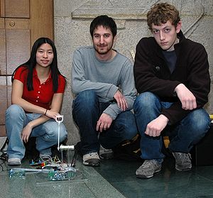
- John Rula (Mechanical Engineering, Class of 2009)
- Alex Wojcicki (Mechanical Engineering, Class of 2009)
- Meredith Chow (Electrical Engineering, Class of 2010)
Introduction
A throwing arm propelled by a Pittman motor is mounted on a turntable and throws the ball into the "hoop." The hoop is wrapped in reflective tape and an IR emitter, receiver pair is used to sense where the IR is reflected most (the hoop with highly reflective tape). An ultrasonic sensor then pings the hoop for the distance of the hoop. With this information, the arm is able to "make a basket."
Mechanical Design
Components
| Part | Part No. | Qty | Vendor | Price (Total) |
|---|---|---|---|---|
| Pittman Motor | GM8712 | 1 | Lab | - |
| RC Servo Motor - Futaba | S3004 | 1 | Lab | - |
| Acrylic .25" Thick, 12"X 12" | 8560K354 | 1 | McMaster | $12.54 |
| Acrylic .25" Thick, 24"X 24" | 8560K357 | 1 | McMaster | $39.63 |
| Corrosion-Resistant Turntable | 6031K17 | 1 | McMaster | $2.42 |
| Fasteners | - | ~20 | Shop supply | - |
Drawings
Electrical Design
Components
| Part | Part No. | Qty | Vendor | Price (Total) |
|---|---|---|---|---|
| PICs | PIC18F4620 | 3 | Lab | - |
| Encoder | LS7083 | 1 | Lab | - |
| H-Bridge | L298N | 1 | Lab | - |
| Ping Ultrasonic Sensor | 28015 | 1 | Lab 5 supply | - |
| IR Emitter | QED123 | 1 | Lab | - |
| IR Phototransistor | LTR-4206E | 1 | Lab | - |
| Diodes | 1N4148 | 4 | Lab | - |
| Resistors | 47.5/150K | 2 | Lab | - |
Circuit Diagram
Code
Results
In the end, the project ultimately succeeded -- baskets could be made. However, better tuning for the motor control and needs to be developed for more consistent results.
Video
Problems Encountered
- Attempting to integrate multiple pics and circuits onto one circuit board did not give good results. Ultimately, we had to use separate boards for each pic. We are not sure what the cause of this is -- perhaps it is noise.
- Motor control was an intense programming effort -- almost a project in its own right. Trying to combine the motor control and distance variation was difficult. Fly back diodes were used to prevent the H-Bridges from burning out. However, we still burned out many H-Bridges.
- The encoder chips also burned out.
- The PING sensor also burned out.
Notes
A few things we might change if we did it again:
- Try another actuator that requires less intense motor control.
- Test whether ribbon cable is too thin for this project's scope (high voltages).
- Figure out why the pics could not be combined.