PIC18F4520: Analog Inputs
Analog-to-Digital Conversion (ADC) is a useful capability of many PIC microcontrollers. This ADC produces a digital value based on the supplied analog voltage, which can then be used with the digital logic of the rest of the PIC. The PIC18F4520 converts analog inputs in the range 0-5V to digital values between 0 and 255 (8-bit resolution).
Available Pins
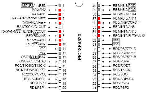
The PIC18F4520 has 13 pins that act as ADCs (shown below). The red pins can be used as analog inputs, while the grey are usually committed to communication or power.
Analog Input Example (ADC)
This section details how to set up an analog input (ADC). There are other examples of ADC conversion capability within other sections as well, as it is utilized often.
Sample Code
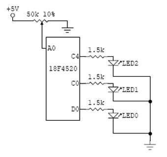
Program to light different LEDs dependent upon position of potentiometer
First include header file with definitions for specific PIC. Set fuses. HS is type of external clock, low voltage programming (LVP) is off, and the watchdog timer (WDT) is off. External clock frequency of 20 MHz is specified.
  #include <18f4520.h>
  #fuses HS,NOLVP,NOWDT,PUT
  #use delay(clock=20000000)
Define pin names to be used in the main program. See header file for currently defined pin names. Also set values for high and low voltage cutoffs. Note that voltages must be defined between 0 and 255 (8 digit binary) which corresponds to a range of 0-5V.
  #define LED_0 PIN_B5
  #define LED_1 PIN_B4
  #define LED_2 PIN_A5
  #define lowcutoff 77   // 1.5V
  #define highcutoff 178   // 3.5V
Begin main body of program.
void main(void) {
Introduce the variable "read" as an 8-bit number (same as int8)
int read;
Setup analog inputs. AN0 can be replaced by ALL_ANALOG, AN0_TO_AN1, AN0_TO_AN11 etc.
     setup_adc_ports(AN0);
     setup_adc(ADC_CLOCK_INTERNAL);
Set which analog channel is active.
set_adc_channel(0);
Use while to set up infinite loop.
while(TRUE) {
Initialize the output LEDs as all off.
        output_high(LED_0);
        output_high(LED_1);
        output_high(LED_2);
Read the analog input and assign the value to the "read" variable.
read = read_adc();
Check the "read" value and light a certain LED depending on its value.
        if(read<lowcutoff)
           output_low(LED_0);
        else if((read>lowcutoff)&(read<highcutoff))
           output_low(LED_1);
        else if(read>highcutoff)
           output_low(LED_2);
     }
  }

